Hey all,
Been reading a few older post on here over the last few days in regards to NAD 3020 and now decide to join forums to ask a few questions and get a better understanding of this unit.
Just recently got donated NAD 3020. The person said that it powered up but no sound and buzzing/humming noise through speakers. To my surprise it actually was playing when I powered it up but as told there is buzzing/humming noise coming through speakers.
Once I was Googling this issue I came across a few post on these forums refereeing to bad/old capacitors. After reading this thread on here: http://www.diyaudio.com/forums/solid-state/35061-nad-3020-hum.html i decided to get new caps and replace them myself. Unfortunately it made no difference and the unit is still emitting the buzzing/humming noise. It's kind of weird as it's quite obtrusive when volume is turned all the way down, if I turn volume up and play music, while it's still there, it actually fades a bit and isn't anymore as obtrusive.
While it's obviously not running at 100% I absolutely love the sound and would like to put it right so I can keep it. Unfortunately I don't have enough know-how in electronics to troubleshoot this myself but not keen to pay someone to repair it without trying to figure it out myself first. I hope you guys can help me here and put me in the right direction.
From a few other bits and bobs I've read about this amp I'm guessing it could be a faulty transformer?
Many thanks in advance!
Andris
After educating myself further I believe the hum also could be caused by blown diode(s)?
Will inspect the amp right now but probably will need some pointers at where to look exactly. 😱
Will inspect the amp right now but probably will need some pointers at where to look exactly. 😱
Last edited:
You are jumping to conclusions, which is not good.
From a faulty transformer to blown diodes.🙁
Sheesh.
Try to narrow down the issue.
Do both channels hum?
There is a pre out & a norm jumper on the rear panel for each channel.
Pull the jumper & run a cable from the pre out to another amp.
Check both channels.
Does that hum?
If it does, then the problem is in the preamp stages.
If not, then the problem is in the power amp section.
There is a 3020A & a 3020B. Find out which one you have.
Schematics can be found here:
3020A: http://p10hifi.net/planet10/manuals/NAD_3020_ServiceManual.pdf
3020B: http://p10hifi.net/planet10/manuals/3020b_schematic.gif
Last edited:
You are jumping to conclusions, which is not good.
From a faulty transformer to blown diodes.🙁
Sheesh.
Thanks for your reply! I'm actually not jumping to any conclusions but as I have a limited knowledge in electronics I'm merely pointing out a few things I've read about on this amp and asking for an advice. Which you obviously have given and it's a starting point for me. 🙂
Do both channels hum?
While playing directly from the 3020 both channels hum, even if volume is turned down to zero. Once I crack the volume up the hum tend to disappear withing music and is less noticeable.
There is a pre out & a norm jumper on the rear panel for each channel.
Pull the jumper & run a cable from the pre out to another amp.
Check both channels.
Does that hum?
If it does, then the problem is in the preamp stages.
If not, then the problem is in the power amp section.
Ok, this is rather strange. I've done what you asked and my findings are as follows. While the 3020 is switched off I can actually hear some music coming through the other amp I've connected to pre out and there is a hum coming through as well (as loud as it would come directly from the 3020) on both channels.
What I'm also finding weird is that while the 3020 still switched off if I turn the volume knob on the 3020 the music level starts increasing. It doesn't sound anywhere good and the music comes through very muffled, surely it shouldn't be like this?
Now, if I switch the 3020 on the output on the other amp goes off i.e. there is no music playing and hum stops too. The switches are different matter and I'm aware that they will need to be cleaned/changed as they make crackling noise but if I turn the volume know back and forth, while the above happening, I get brief sound through "power amp" connected to the 3020 accompanied by occasional loud pop/crackle. 😕
There is a 3020A & a 3020B. Find out which one you have.
Schematics can be found here:
3020A: http://p10hifi.net/planet10/manuals/NAD_3020_ServiceManual.pdf
3020B: http://p10hifi.net/planet10/manuals/3020b_schematic.gif
I'm pretty sure it's the 3020A as it matches the picture in schematics.
I hope I've explained my findings clear enough and hopefully it's enough to enable you give me some further advice but if there anything else you'd need to know please let me know.
Many thanks,
Andris
The legend on the first schematic referred to states only 3020. There are a few misnamed schematics around. Search another recent thread here with the same issue and note that there hasn't been a schematic showing the A version posted. If you have an amplifier that does not have 3020A marked on the rear label and or front panel, then obviously it's not a 3020A. Check the labels, read the PCB rev.no, compare googled pics and be certain.
Both models have similar electronics but a different positioning of main electrolytic caps so the PCB layout differs, IIRC.
Both models have similar electronics but a different positioning of main electrolytic caps so the PCB layout differs, IIRC.
Last edited:
Sounds like a broken ground trace. The first thing to do is find out if the fault is in the preamp or the power amp. Try removing the jumper links and connecting a source with a volume control (eg a portable mp3 player or suchlike) to the NORMAL IN.
The legend on the first schematic referred to states only 3020. There are a few misnamed schematics around. Search another recent thread here with the same issue and note that there hasn't been a schematic showing the A version posted. If you have an amplifier that does not have 3020A marked on the rear label and or front panel, then obviously it's not a 3020A. Check the labels, read the PCB rev.no, compare googled pics and be certain.
Both models have similar electronics but a different positioning of main electrolytic caps so the PCB layout differs, IIRC.
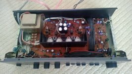
I'm now getting confused. From several threads I've read on the 3020 over last few days I was under impression that the original 3020 design had a separate little PCB for pre amp section and the 3020A had the pre amp section on the main PCB.
Confused now but here is the pic of the one I have.
Sounds like a broken ground trace. The first thing to do is find out if the fault is in the preamp or the power amp. Try removing the jumper links and connecting a source with a volume control (eg a portable mp3 player or suchlike) to the NORMAL IN.
I just tried this and no hum what so ever so looks like the fault, whatever it is lays within pre amp section. So do you think it could be a broken ground trace? What should check next?
Attachments
Actually I now recall this is typical of bad capacitors in the preamp circuit. I'm still not sure which amp you actually have here but they are both similar.
I'd start by replacing the capacitors in the preamp. If it's a 3020 or A, these would be C513-C518. If it's a B, it'd be C513, C514, C517, C518, C519, C520.
You mention that the preamp out worked even without power. This is possible, the signal can flow via some resistors and coupling capacitors, it will just be unamplified. I suspect this is why in the 3020B they added the JFET's Q509 and Q510 to shut off the output when there's no power.
Broken PCB traces on the preamp inputs is a very common problem with early NAD 3020 models. The traces adjacent to the input jack connections is the obvious location. Inspect them closely, if necessary with a magnifying glass, as this is the likely spot where mechanical stress due to tugging on leads in the weak sockets, and the simple fact that this the point of physical connection beteen front and rear panels and the focus of an mechanical stress between them . Carefully test your findings by shorting across a possible crack or break with an insulated, fine screwdriver blade to see if it is so. A simple jumper or clip lead or even a multimeter lead used to bridge solder connections only on the same trace is another way of doing the same thing. Note that there will be a thin lacquer over the copper to prevent corrosion and a little scratching may be necessary to get reliable contact.
BTW, you haven't said what the model number on the front panel identifies the model as. If you Google "NAD 3020A pics" you get a number of different looking models, some with different transformer mounting, capacitor position, artwork etc. It varies with the country of distribution, too.
A very odd concoction model, even though most of the examples there really are identified as 3020A. However, this does not alter the basic problem you have and is only necessary if you can't otherwise identify or locate parts.
Actually I now recall this is typical of bad capacitors in the preamp circuit. I'm still not sure which amp you actually have here but they are both similar.
I'd start by replacing the capacitors in the preamp. If it's a 3020 or A, these would be C513-C518. If it's a B, it'd be C513, C514, C517, C518, C519, C520.
You mention that the preamp out worked even without power. This is possible, the signal can flow via some resistors and coupling capacitors, it will just be unamplified. I suspect this is why in the 3020B they added the JFET's Q509 and Q510 to shut off the output when there's no power.
Thanks, I'll study the capacitors tonight once I got home from work.
Broken PCB traces on the preamp inputs is a very common problem with early NAD 3020 models. The traces adjacent to the input jack connections is the obvious location. Inspect them closely, if necessary with a magnifying glass, as this is the likely spot where mechanical stress due to tugging on leads in the weak sockets, and the simple fact that this the point of physical connection beteen front and rear panels and the focus of an mechanical stress between them . Carefully test your findings by shorting across a possible crack or break with an insulated, fine screwdriver blade to see if it is so. A simple jumper or clip lead or even a multimeter lead used to bridge solder connections only on the same trace is another way of doing the same thing. Note that there will be a thin lacquer over the copper to prevent corrosion and a little scratching may be necessary to get reliable contact.
BTW, you haven't said what the model number on the front panel identifies the model as. If you Google "NAD 3020A pics" you get a number of different looking models, some with different transformer mounting, capacitor position, artwork etc. It varies with the country of distribution, too.
A very odd concoction model, even though most of the examples there really are identified as 3020A. However, this does not alter the basic problem you have and is only necessary if you can't otherwise identify or locate parts.
I'll have look at PCP traces as well as you suggested, thanks.
Model wise it says NAD 3020 (no any other letters) on fascia. If it helps to identify it further then Serial Number is A3253294.
No, 3020 is 3020, not 3020A or B revisions. This appears to be the original 3020 model. Note that for UK distributed products, AFAIK:
1) Location of the 4 large electrolytics (compare with position on 3020B layout diagram)
2) The mounting of the transformer to the rear panel.
3)There's no 8/4 ohm speaker load switch, that swaps power transformer tappings on later models.
4)The front panel logo position is further from the left side and 3020 means only what it says.
5) Q509,510 (the JFET muting switches in the 3020B) are just not there.
6)The separate PCB you referrred to is that of the power meter only, not the preamp. (located above volume pot.)
There are more differences but that should do to distinguish them. Common part numers are retained from the 3020 and this is why you see the same capacitor reference numbers. This helps if using the wrong schematic, provided you read the label and are mindful of which model you are dealing with. There are plenty of free schematics for these on the web, so there should no problem, taking care that the Google engine doesn't just bundle all variants containing the search term together. An easy mistake, to assume the engine can sift for all your search priorities with only one reference.
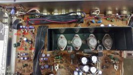
This example appears to have had a replacement part or two already, as it should have, after 30 odd years. (C513 and apparently the main power supply electrolytics, and the bias sense transistors, Q609,610 may have been remounted for some reason, perhaps in error.)
FWIW, I subscribe to url=http://www.hifiengine.com/library/nad/3020.shtml?destination=node%2F3950]NAD 3020 | Owners Manual, Service Manual, Schematics, Free Download | HiFi Engine[/url] for most schematics but there are some better quality free downloads with more enlightened service agencies for other brand products, if needed.
1) Location of the 4 large electrolytics (compare with position on 3020B layout diagram)
2) The mounting of the transformer to the rear panel.
3)There's no 8/4 ohm speaker load switch, that swaps power transformer tappings on later models.
4)The front panel logo position is further from the left side and 3020 means only what it says.
5) Q509,510 (the JFET muting switches in the 3020B) are just not there.
6)The separate PCB you referrred to is that of the power meter only, not the preamp. (located above volume pot.)
There are more differences but that should do to distinguish them. Common part numers are retained from the 3020 and this is why you see the same capacitor reference numbers. This helps if using the wrong schematic, provided you read the label and are mindful of which model you are dealing with. There are plenty of free schematics for these on the web, so there should no problem, taking care that the Google engine doesn't just bundle all variants containing the search term together. An easy mistake, to assume the engine can sift for all your search priorities with only one reference.
This example appears to have had a replacement part or two already, as it should have, after 30 odd years. (C513 and apparently the main power supply electrolytics, and the bias sense transistors, Q609,610 may have been remounted for some reason, perhaps in error.)
FWIW, I subscribe to url=http://www.hifiengine.com/library/nad/3020.shtml?destination=node%2F3950]NAD 3020 | Owners Manual, Service Manual, Schematics, Free Download | HiFi Engine[/url] for most schematics but there are some better quality free downloads with more enlightened service agencies for other brand products, if needed.
Last edited:
Thanks Ian for your input once more. The points you've mentioned match the amplifier I got here and I also had a look at the service manual available on hifiengine and I'm pretty certain now that it's the original 3020.
It kind of contradicts with what jaycee said earlier in regards to the pre amp caps:
but after having a look in the service manual looks like the caps in question really are C513, C514, C517, C518, C519, C520 (as already discovered on the map), jaycee was referring to B model in regards to these caps, mistake?
Another thing I've discovered is that there is a discrepancy in the capacitor values I've found in the manual as the caps in the amp are slightly different, probably replaced already at some point?
According to the manual the capacitor values should be:
C513 - 47uF 10V
C514 - 47uF 10v
C517 - 47uF 25v
C518 - 47uF 25V
C519 - 47uF 10V
C520 - 47uF 10V
but as per my previous post the capacitor values installed are:
C513 - 47uF 16V
C514 - 47uF 16v
C517 - 47uF 25v
C518 - 47uF 25V
C519 - 100uF 10V
C520 - 100uF 10V
If there are no other immediate suggestions I'll proceed to order the replacement capacitors? I'm now confused which are the correct capacitor values, I'm guessing the ones mentioned in the manual? In having said that C517-C520 looks like the original capacitors? Could it be that there is a mistake in the manual?
At the same time I'd also inspect for broken PCB traces.
It kind of contradicts with what jaycee said earlier in regards to the pre amp caps:
I'd start by replacing the capacitors in the preamp. If it's a 3020 or A, these would be C513-C518. If it's a B, it'd be C513, C514, C517, C518, C519, C520.
but after having a look in the service manual looks like the caps in question really are C513, C514, C517, C518, C519, C520 (as already discovered on the map), jaycee was referring to B model in regards to these caps, mistake?
Another thing I've discovered is that there is a discrepancy in the capacitor values I've found in the manual as the caps in the amp are slightly different, probably replaced already at some point?
According to the manual the capacitor values should be:
C513 - 47uF 10V
C514 - 47uF 10v
C517 - 47uF 25v
C518 - 47uF 25V
C519 - 47uF 10V
C520 - 47uF 10V
but as per my previous post the capacitor values installed are:
C513 - 47uF 16V
C514 - 47uF 16v
C517 - 47uF 25v
C518 - 47uF 25V
C519 - 100uF 10V
C520 - 100uF 10V
If there are no other immediate suggestions I'll proceed to order the replacement capacitors? I'm now confused which are the correct capacitor values, I'm guessing the ones mentioned in the manual? In having said that C517-C520 looks like the original capacitors? Could it be that there is a mistake in the manual?
At the same time I'd also inspect for broken PCB traces.
Forget the rest, change C531 and C533. They form the voltage doubler for the preamp stage and give problems. Make sure you fit 105° types and always fit the same voltage rating!
Forget the rest, change C531 and C533. They form the voltage doubler for the preamp stage and give problems. Make sure you fit 105° types and always fit the same voltage rating!
Christ on a bike, looks like I'll have replaced all the capacitors by the time I've finished with this thing. 😀
By saying "fit the same voltage rating" I'm guessing you are referring to follow the service manual entries (C531 - 47uF 63V & C533 - 47uF 50V) instead of matching the voltage rating for the two caps, let's say both 63V?
Sorry, for all the noob questions but I'm learning this stuff as I go along.
Will order some higher grade caps next week but I've checked my local Maplin and they have both caps in stock but only one of them is 105° but it shouldn't harm to fit 85° for the time being to at least try out your suggestion. Will try to fit them tonight to see if this is a culprit of the issue.
I think both at 63v will be OK but when I often read about people changing a 10u 16v for a 10u 100v that is silly as they are a different construction and ESR etc.
OMG, you won't believe this.
Changed the caps Jon suggested - C531 and C533, plugged the amp back in, still humming like mad. 😡
I though, well I need to order more caps to replace C513, C514, C517, C518, C519, C520 as suggested earlier but then decided to inspect for broken PCB traces as suggested by Ian. I didn't have a magnifying glass at this stage so was just using bright torch and eyeing the board as close as I could. Went over several times but could not see any interruption in traces but then noticed that two of the Phone Input soldering points have one edge ever so slightly lifted off the PCB.
I thought that it surly cannot be the culprit of the problem and I was convinced that there is still contact made and I was going to leave it but then I thought, what the hell, I might as well re-solder the contacts while I have the soldering iron out.
Plugged in the amp afterwards and it greats me with absolute silence. 😱 Plugged in source and it plays music like there is no tomorrow.
The moral of this story is that sometimes it's more simpler than one might think. 🙂
Thank you all for your input it was much appreciated.
And now you have one of the most musical amps made. I still got mine, on the shelf, i am playing with more expensive equipment. I love the sheer musicality of the 3020, it is hard to find elsewhere.
In fact, before I sign off, I just would like to clarify the capacitor values discrepancy I've mentioned earlier.
Just in a case I ever need replacing any of the caps, as mentioned before C513 & C514 is 47uF 16V instead of 47uF 10V as suggested by the service manual. It looks like these two caps have been replaced at some point and my understanding now is that if they have slightly higher voltage rating it's nothing to worry about?
On other hand the caps C517 - C520 all look originals and I can't see any trace of any re-soldering. While the caps installed in C517 & C518 matches the suggested values in the service manual the caps installed in C519 & C520 are 100uF 10V instead of recommended 47uF 10V. Should I be concerned about this or is it OK to leave them as it is?
My further concern is that if I ever need to change these two caps what values should I uses, as from what I can gather while it's acceptable to use slightly higher value caps it's not to use lower value. So let's say if I follow the manual and replace 100uF 10V (installed) with 47uF 10V (suggested) and if it was a printing mistake in the manual I could mess up things, could I?
On a completely different matter what's the best way to clean the switches to get rid of any crackle? I believe there is some sort of spray?
Use Servisol Switch Cleaner or if they are really bad 3in1 Lawnmower oil. Yes, it works a treat!
C531 and 533 are the main ones to change!
C531 and 533 are the main ones to change!
- Status
- Not open for further replies.
- Home
- Amplifiers
- Solid State
- NAD 3020 - faulty but is it worth fighting for it?