So I have a mouser order going in shortly and I’ve decided to give the little 1-bit DAC CDP a refresh. I’ve owned this since new and so I feel I owe it a little refresh to see out the remainder of it’s life.
Inside the MC100 there’s a small power board with a common mode choke (no X caps) with power rectificiation. A small torroid sits miles away. This is a class 2 power device so there’s no protective earth thus the power board doesn’t have Y caps to earth as the only earth is via the shielding connection on the RCA connectors. So no IEC filter without messing with earth (nope not doing that) but I will add a WIMA X2 between live and neutral in front of the common mode choke.
The power rectifier caps I replaced previously after it blew an internal fuse (tray binding). They are now CDE and Panasonic chosen for the handling of 100Hz. That replacement (slightly larger capacitance but not much) improved the sound - especially the bass which then got me thinking for a general refresh of the electrolytics.
The proposed changes are:
Power board
Add WIMA 0.33uF X2 class is my initial thought although I will look for a 400+Vac option here as my mains can hit 252Vac. The PCM22.5 of the 275Vac variant of this has a lower impedance at a point I seem to have noise in the house and this would allow the mains EMI noise to bypass so I'm looking for a high voltage version. The 450Vac MKP-X2 variant is available but 1uF. X2 would mean if there's an over volt, if the cap fails open then there's no issue, but if the cap would short live and neutral and the breaker/IEC power inlet fuse should blow.
I'm not adding any Y class caps because the only route to ground is via the RCA shielding and this is a class 2 device - the route for any internal failure that gets beyond the the isolation is to RCA ground then the amp ground PE pin. There's no PE pin in this CDP (hence adding a IEC filter would need a class 2 medical variant that does not ground the chassis, but searching none of these options have inbuilt fuses! Not worth the hassle with standard IEC filters and insulating the filter metal case from the case and would probably break the forum rules).
Main board supply changes
10V Samsung SSL 220uF -> 16V Panasonic EUU FM 330uF
50V Samsung SSL 100uF -> 50V Panasonic EUU FM 180uF
63V unknown brand 10uF -> 63V Panasonic EUU FR 47uF (10uF sounds more like noise reduction) or the older TA-A series 22uF (not fully decided)
BB OPA2640AP output stage power decoupling (film/polyester caps seem to be next to the chip so we dont need to get too overboard, just a small bunk):
25V Rubicon sky blue 100uF -> 25V Panasonic EEH AZA (organic polymer) 150uF. The low frequency derating of 0.1 (yes 0.1!) is fine as we’re well below that with the OPA2640.
Laser assembly
6.3V nichicon 100uF -> 6.3V nichicon UPW 100uF
I did look at the crystal (whilst pulling and refreshing components). An AEL 33.8688 (oscillator 5V with a 50pF max loading and 100ppm). However this is refresh is to keep the CDP running for the remainder of it’s life. If I want the change the sound then adding a 24bit DAC to replace the Sony 1bit onboard DAC would be the way to go. I’d probably look to a AKM DAC chip with a class A output stage.
I have a stock check as I want to put some power supply PCBs for other projects along with my ADC clock PCB on the same PCB so I’m not wasting the etch. Once those final components are confirmed I’ll put in the mouser order.
Edit: just noted the WIMA MKP-X2 is rated at 400Vac by mouser but in the datasheet it's 305Vac. Hmm I really need 380V peak. WIMA MKX (X1) is rated in the datasheet for 440Vac... phew.
Attachments
Last edited:
The 63V 10uF caps got me thinking and some research has proved there's something I need to take into account - ringing and dampening from the digital and opamp demands and the interactions with the other caps. For this reason it may be that I may get a selection of caps and use a test CD to test the opamp supplies at different frequencies and attach the scope to ensure I've not made the supplies worse.
For this reason I may opt to keep close to the 60V 10uF caps and possibly normal ESR to prevent ringing.
Coincidentally, I’ve been looking ferrite beads and clocks for a different project and the same similar issue appears here too.
The OPA2640 datasheet suggests that a 1uF tantalum cap is all that is required, which would be higher ESR but i would not be convinced it would help filter high frequency. The board has a 100nF close.
I really need to check the power supply schematic by looking at the underside. There’s a regular pattern of larger cap, transistor, small cap then ceramic/film, which smells like a series or shunt power supply. I suspect a shunt. So that’s today’s task.
Indeed. I'm looking at the opamp power supply - there is one for both opamps, each opamp has it's own MKC 100nF but then they join to a single rail that has two sequential stages that's only visible on the underside (centre of the attached image there's a pair of transistors).
Attachments
It makes me weird to see a myryad pcb that is not charred.
I worked on several amps of the brand and they are almost all cooked because part of the circuit remains live even if the switch is off.
At least cd players don't have these problems.
I worked on several amps of the brand and they are almost all cooked because part of the circuit remains live even if the switch is off.
At least cd players don't have these problems.
It makes me weird to see a myryad pcb that is not charred.
I worked on several amps of the brand and they are almost all cooked because part of the circuit remains live even if the switch is off.
At least cd players don't have these problems.
You have me thinking as there's a soft power and a AC power switch. The AC power switch does switch the AC input but the soft may simply switch the relays. There's no switching component (relay or semiconductor) on the power board where the rectification occurs so the caps on that board are definitely rectifying all the time the AC switch is switched to on, regardless of the soft power switch. There are two relays - one near the power supplies and one that switches the analogue output. So it could possibly keep the power supplies fully powered I should check.
Suspicion was correct- the ±30Vdc and ±15Vdc supplies are always on, the 5V too but the soft switch switches the 5V for the DAC from 3V (off) to 5V (on). So the analogue portion of the amp is always powered on with the AC switch on and the digital side runs on reduced voltage but is always on too.
Last edited:

I found a couple of lower reading caps. So I've got the BOM for those sorted - just need to make sure they have enough lead length as all the PCB sites for the caps have 5mm spacing which is good but some of the caps need longer leads to space across them as they do now. So next to sort out my clock BOM for the ADC and then the entire lot gets ordered.
So the parts arrived last night.
First was replacing this Nichicon 6.3V 100uF on the CD head. I tested straight after and the drive worked (no audio check at this stage) but seeked and read the index perfectly.

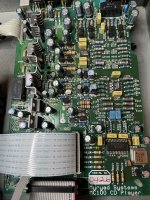
Next up was the main board.. 35 capacitors later.. looks very Panasonic..

The majority of the caps fitted perfectly (there's one tight squeeze top right) but all were meant to fit the original cap diameter and lead spacing. The board weighs more I noted. I've not bunked the capacitance that much but given there's 16 caps that have changed from 220uF to 470uF, I was a little concerned with inrush.
In fact I'd previous changed the power board caps to .. Panasonics too. I'd increased the capacitance of one a little. Only issue with this was an originally dry/cracked solder joined on the power that was arching and the connector (I don't know the type but it's horrid) which is now hot glued.

I powered up the board without the mechanism or front panel connected first. I could have swore I saw a puff of smoke out the corner of my eye. Whatever it was wasn't lingering.
I plugged the scope into right channel and played the focal-test-cd to perform an initial test. All good.
I plugged into the left channel and played.. nothing. zip. The DC level remained low as the right channel (~0.1-0mV). I pulled out the Brymen and prodded.. first check is - have I blown an opamp?
1. Check the power - quick check of the power supply rails (handy the put marks for the test points!) - the ±30V rails ok, ±15V rails ok, +5V rail ok, +7.5V rail ok. Well the power's ok. No ripple, no nasties simply smooth DC.
2. Check the Opamps - power rails ~15V good. I then checked the output of each opamp. Interesting, one output shows a -14Vdc. This doesn't necessarily show a dead opamp. I noted that on start up the opamp output starts at 0V then slowly drifts and settles at -14Vdc, no jumps, just slow drift down.. This sounds like a biasing issue or an input issue not the opamp. The other opamp in the package seemed to be running fine.
This CDP is simple - there is one power rail to both opamps.
3. Hunt for the bias problem - I went through and check the voltages transistor, all seemed good.. I checked the underside for any shorts.. nope I can't see any.. then I noted this with one of the caps - a small dent.


Checking the previous photos before the procedure, sure enough the cap did not have a dent.. pants. My attention turned to the cap - was it shorting the bias and thus causing the opamp to simply output the rail voltage? I switched to cap mode on the DMM.. Disconnected.. hmm .. I test it's partner on the other channel - it shows a value.
So my hypothesis is that at some point I've punctured the cap - a 3.3nF F160 (I believe these are Phillips Milspec) vintage from the ~1989 era. On a plus side this is on the filtering and shaping filter. I have located some non-bay UK based identical 3.3nF J160 milspec replacements that are almost identical, however I don't know the difference between F and J identifier specifications (if anyone has a datasheet for these I would be most grateful).
Next option tonight will be to test the cap more, see if it's shorting to ground and is the issue. I'll also connect up the ADC to take some measurements from the test cd.
On a positive note, the CDP seems to have perked up. The mechanism is now behaving itself and is more positive. The output of the working channel is looking very good.
First was replacing this Nichicon 6.3V 100uF on the CD head. I tested straight after and the drive worked (no audio check at this stage) but seeked and read the index perfectly.
Next up was the main board.. 35 capacitors later.. looks very Panasonic..
The majority of the caps fitted perfectly (there's one tight squeeze top right) but all were meant to fit the original cap diameter and lead spacing. The board weighs more I noted. I've not bunked the capacitance that much but given there's 16 caps that have changed from 220uF to 470uF, I was a little concerned with inrush.
In fact I'd previous changed the power board caps to .. Panasonics too. I'd increased the capacitance of one a little. Only issue with this was an originally dry/cracked solder joined on the power that was arching and the connector (I don't know the type but it's horrid) which is now hot glued.
I powered up the board without the mechanism or front panel connected first. I could have swore I saw a puff of smoke out the corner of my eye. Whatever it was wasn't lingering.
I plugged the scope into right channel and played the focal-test-cd to perform an initial test. All good.
I plugged into the left channel and played.. nothing. zip. The DC level remained low as the right channel (~0.1-0mV). I pulled out the Brymen and prodded.. first check is - have I blown an opamp?
1. Check the power - quick check of the power supply rails (handy the put marks for the test points!) - the ±30V rails ok, ±15V rails ok, +5V rail ok, +7.5V rail ok. Well the power's ok. No ripple, no nasties simply smooth DC.
2. Check the Opamps - power rails ~15V good. I then checked the output of each opamp. Interesting, one output shows a -14Vdc. This doesn't necessarily show a dead opamp. I noted that on start up the opamp output starts at 0V then slowly drifts and settles at -14Vdc, no jumps, just slow drift down.. This sounds like a biasing issue or an input issue not the opamp. The other opamp in the package seemed to be running fine.
This CDP is simple - there is one power rail to both opamps.
3. Hunt for the bias problem - I went through and check the voltages transistor, all seemed good.. I checked the underside for any shorts.. nope I can't see any.. then I noted this with one of the caps - a small dent.
Checking the previous photos before the procedure, sure enough the cap did not have a dent.. pants. My attention turned to the cap - was it shorting the bias and thus causing the opamp to simply output the rail voltage? I switched to cap mode on the DMM.. Disconnected.. hmm .. I test it's partner on the other channel - it shows a value.
So my hypothesis is that at some point I've punctured the cap - a 3.3nF F160 (I believe these are Phillips Milspec) vintage from the ~1989 era. On a plus side this is on the filtering and shaping filter. I have located some non-bay UK based identical 3.3nF J160 milspec replacements that are almost identical, however I don't know the difference between F and J identifier specifications (if anyone has a datasheet for these I would be most grateful).
Next option tonight will be to test the cap more, see if it's shorting to ground and is the issue. I'll also connect up the ADC to take some measurements from the test cd.
On a positive note, the CDP seems to have perked up. The mechanism is now behaving itself and is more positive. The output of the working channel is looking very good.
So I've answered my questions 🙂
The resistance across the damaged 3.3nF is 0.011R and falling.. its partner on the other channel measures in the Mohms. So that's a dead short cap.
Secondly the J vs F - F is 1% and J is 5%. So the option is to test all the 5% ones I've ordered (a bag of 5) and see which comes closest. Final option is to simply buy a pair of Vishay 160V 1% axial caps and swap those out.
It's odd that the other silver foil caps measure as 32Kohm.. and some of their partners measure in Mohm so I may be tempted to replace the lot as they're clearly on the leaky side unless there's a secondary route. However logically either the resistors are dead or the caps are dead 🙂
Whilst I wait for the new caps, I may replace them with some 2.2nF FKP1s I have (1.2kV!) which are about the same size and see what the difference is via testing.
Last edited:
So I'm using the focal test cd track 27 (1KHz) on repeat for this test. The spur next to the 1Khz is caused by the track repeat seek. Also to note is the noise bump at the top of the audio range. The test equipment has had at least 1h30 to warm up - that's the signal generator, the ADC (at 100mA draw) using single ended connection with one connection BNC shorted), the CDP sat in operation.
4M FFT and 16 averages. I used 4Vrms FS but it's likely to very slightly out of peak from the real FS.
So there's a small difference between the channels - the channel with original 3.3nF.

The channel with WIMA 1.2kV 0.22nF FKP1 replacing the damaged cap - there's a very slight improvement in noise floor and the noise bump reduces slightly:

For reference and comparison, 1kHz 1Vrms calibrated with the signal generator before the test:

Now looking (for the first time) at the CDP's "hump" at the very top end in the audio spectrum (I can hear high frequencies still) and listening with the CHN50s there's a little shrillness on some notes).. may be it's been brought to my attention.
Last FFT is the noise floor from the CDP before the test without the CD playing (original channel):

4M FFT and 16 averages. I used 4Vrms FS but it's likely to very slightly out of peak from the real FS.
So there's a small difference between the channels - the channel with original 3.3nF.
The channel with WIMA 1.2kV 0.22nF FKP1 replacing the damaged cap - there's a very slight improvement in noise floor and the noise bump reduces slightly:
For reference and comparison, 1kHz 1Vrms calibrated with the signal generator before the test:
Now looking (for the first time) at the CDP's "hump" at the very top end in the audio spectrum (I can hear high frequencies still) and listening with the CHN50s there's a little shrillness on some notes).. may be it's been brought to my attention.
Last FFT is the noise floor from the CDP before the test without the CD playing (original channel):
Last edited:
Caught a moment on the MC100 and A220 that demonstrated how much clearer it seems to play. There's a passage on a Megadeth album, So Far So Good So What, that has the music transfer to a radio in a car and then have the car drive off. You can hear a load more in this passage. Part the A220 upgrade with the new op amps but also the the new refresh.
The down side with any surgery is that the CD12 mechanism is loosing alignment as there's something bumping periodically as the CD rotates. This eventually causes issues with the CD playing. This is most likely the physical mechanism, so a change I think is in order.
The down side with any surgery is that the CD12 mechanism is loosing alignment as there's something bumping periodically as the CD rotates. This eventually causes issues with the CD playing. This is most likely the physical mechanism, so a change I think is in order.
My J160s have arrived, there are pairs that are within 0.01nF of each other although they read 3n43, they would be perfect for the 3n3. They also have resistance, thus no measurable leakage. However I’m now in a mind to keep the FKP1s in there instead.
I have a holiday break before starting the new job - quiet in the house so I've had some time.
So I've traced the issue of the CD issues I think. I've resisted getting the soldering iron out immediately.
The symptoms are - high tracks (ie outter edge) you can hear the focus coils going, then with the top off the CD you can see the spin up and tracks showing some CD wobble. I normal have the A220 sat on top so the CDP with it's hot output stage and the A220 heatsink just above the CD mechanism cooks the top which makes the CDP problem of tracking the CD to the point you can hear the errors in the audio stream in time with the rotations. Also sometime the CD motor refuses to start completely and the CD is ejected. A data stream corruption should be easy to spot on the SPDIF output with a scope.
Logically as the CD head is mounted on the same metal chassis (and I've not touched the motor) this wobble is not a chassis to motor but more likely the CD spindle bearing or the lubrication (ie hardened grease/dirt). This would explain the cyclic vertical displacement of the CD when playing.
Previously the CDP had issues ejecting after a long break of use, so I think the mechanism itself needs a service.
Any thoughts?
Hi guys! It seemed that My mcd200 toroid was dead .As they share same toroid, so could anyone give me big help to point out its pinouts for each colorful lead and maybe I can rewire or order a custom made one to let it alive! Thanks in advance!!
Cheers
Fc2fc

Cheers
Fc2fc
I can have a look next week, unfortunately I’m a little busy atm.
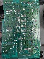
That power board looks almost identical to the mc100.
That power board looks almost identical to the mc100.
- Home
- Source & Line
- Digital Source
- Myryad MC100 (1997) refresh progress thread