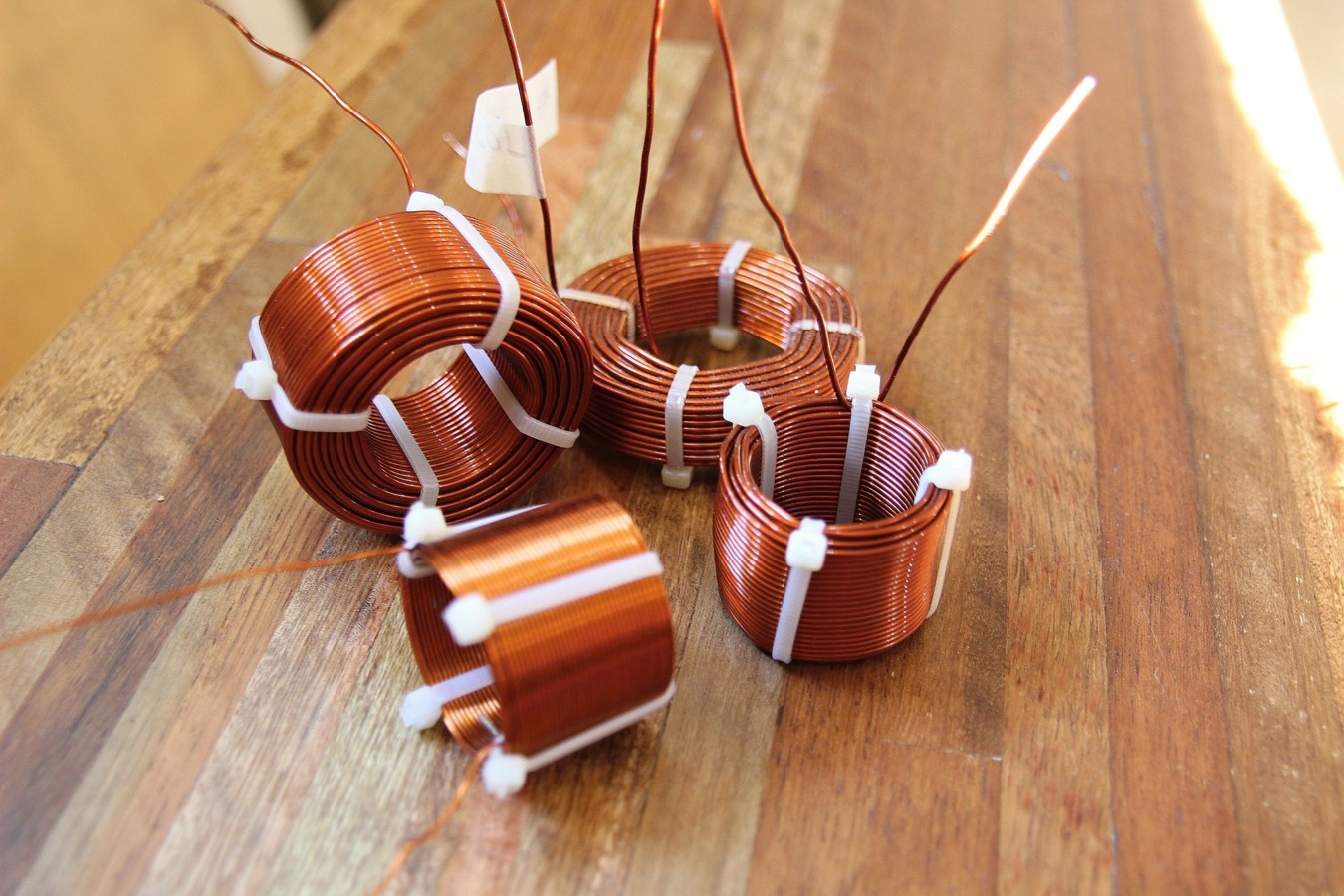
Very nice job .. I did made a winding lathe ... long time ago but I did not build a universal core ... I made woodden core ... one for each coil I made .... they still stand in the cross over in the living room .... one core ...one coil ..
You should see this documentation about coil optimisation
Brooks Coil and Calculator - Ness Engineering Inc.
Brooks Coil and Calculator - Ness Engineering Inc.
I love:
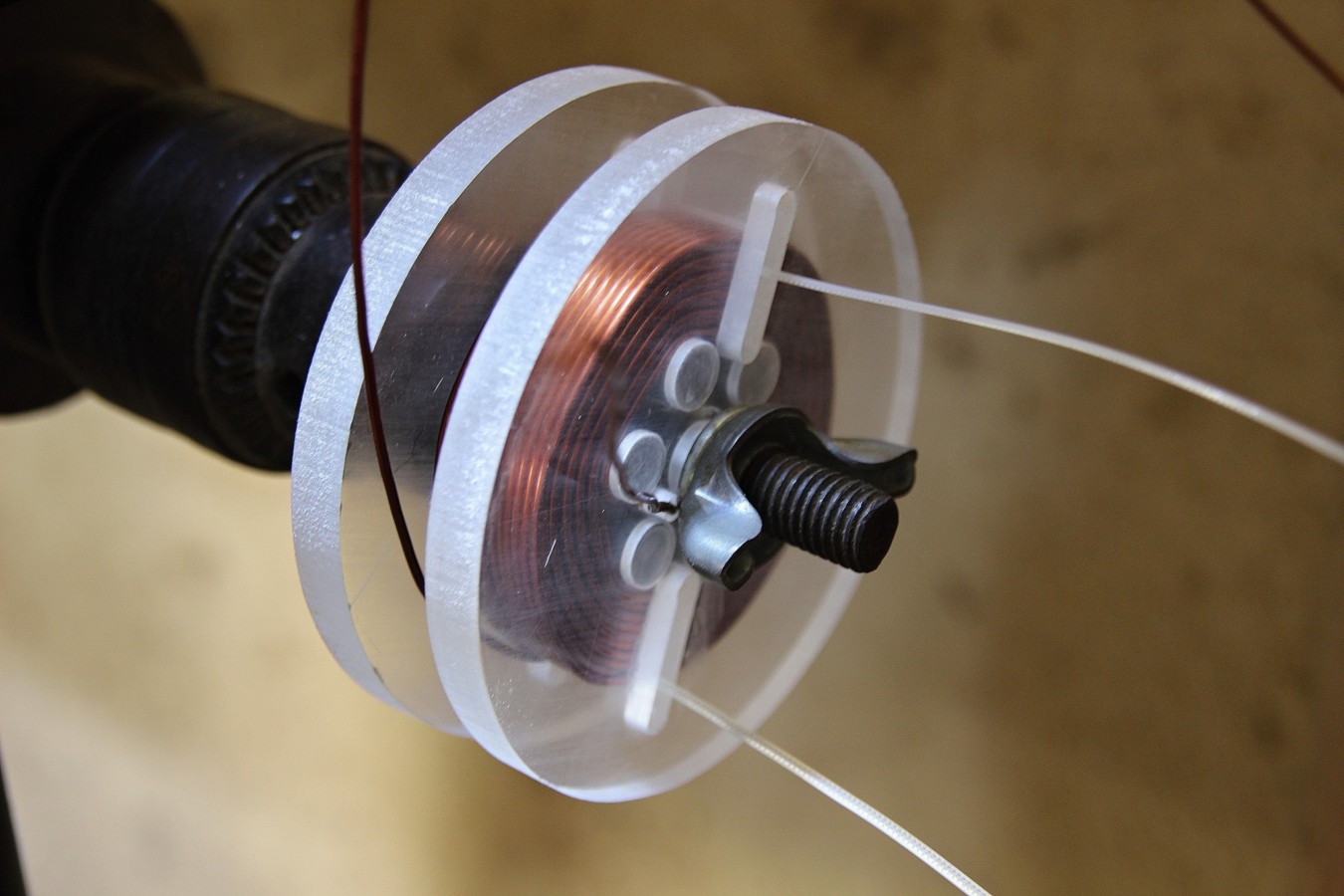
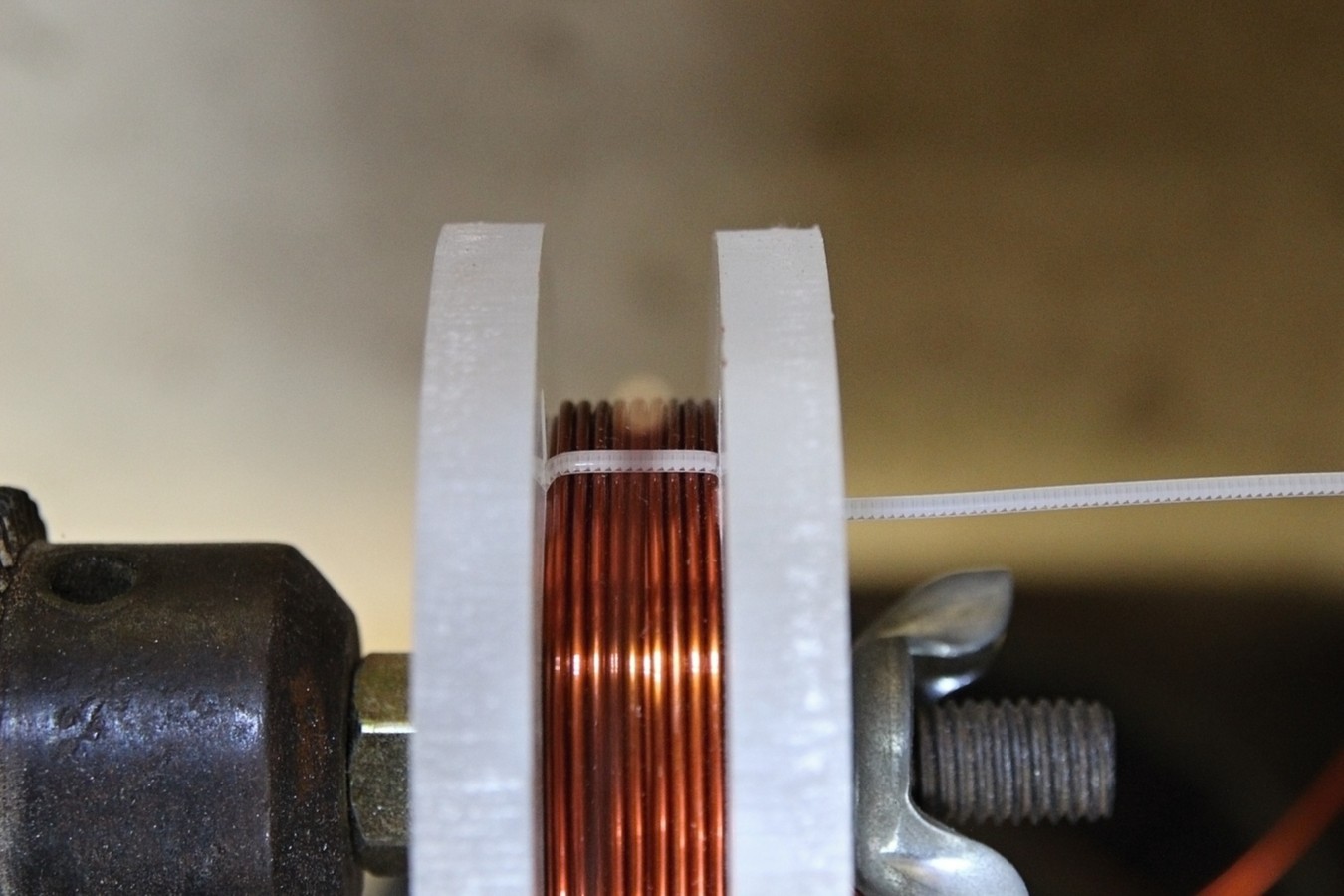
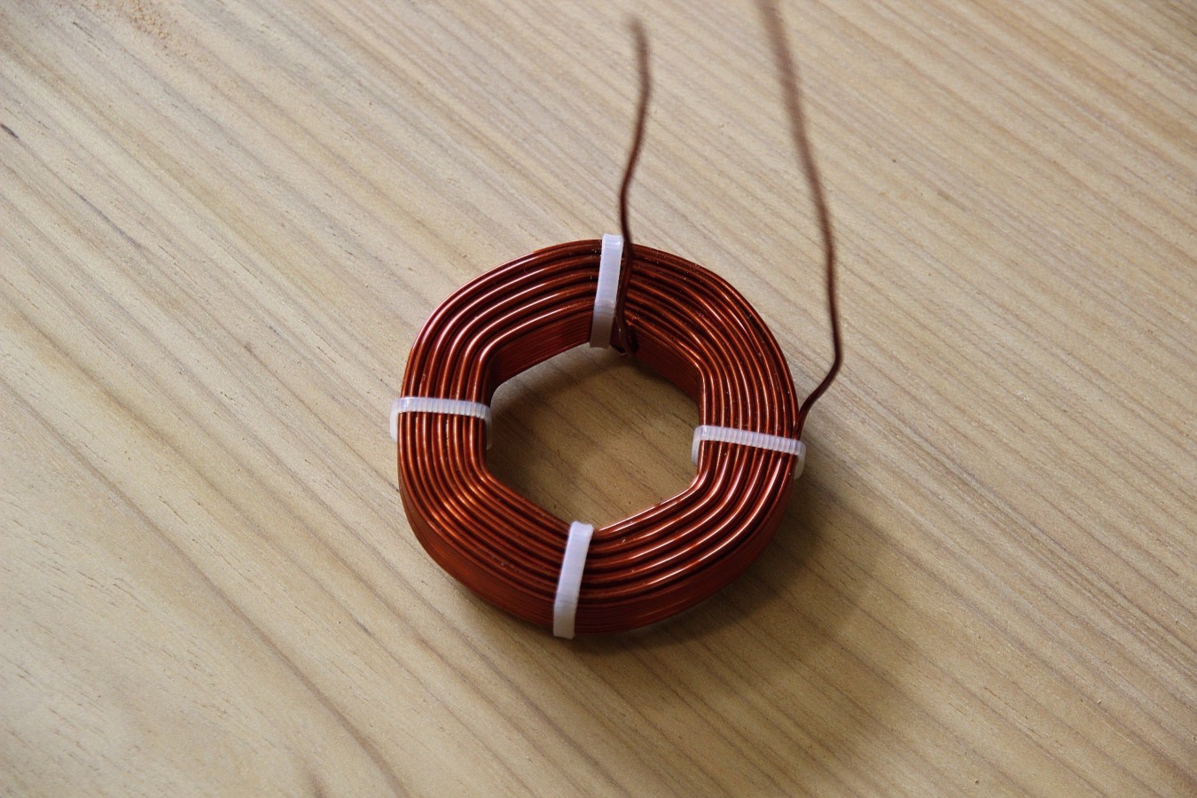
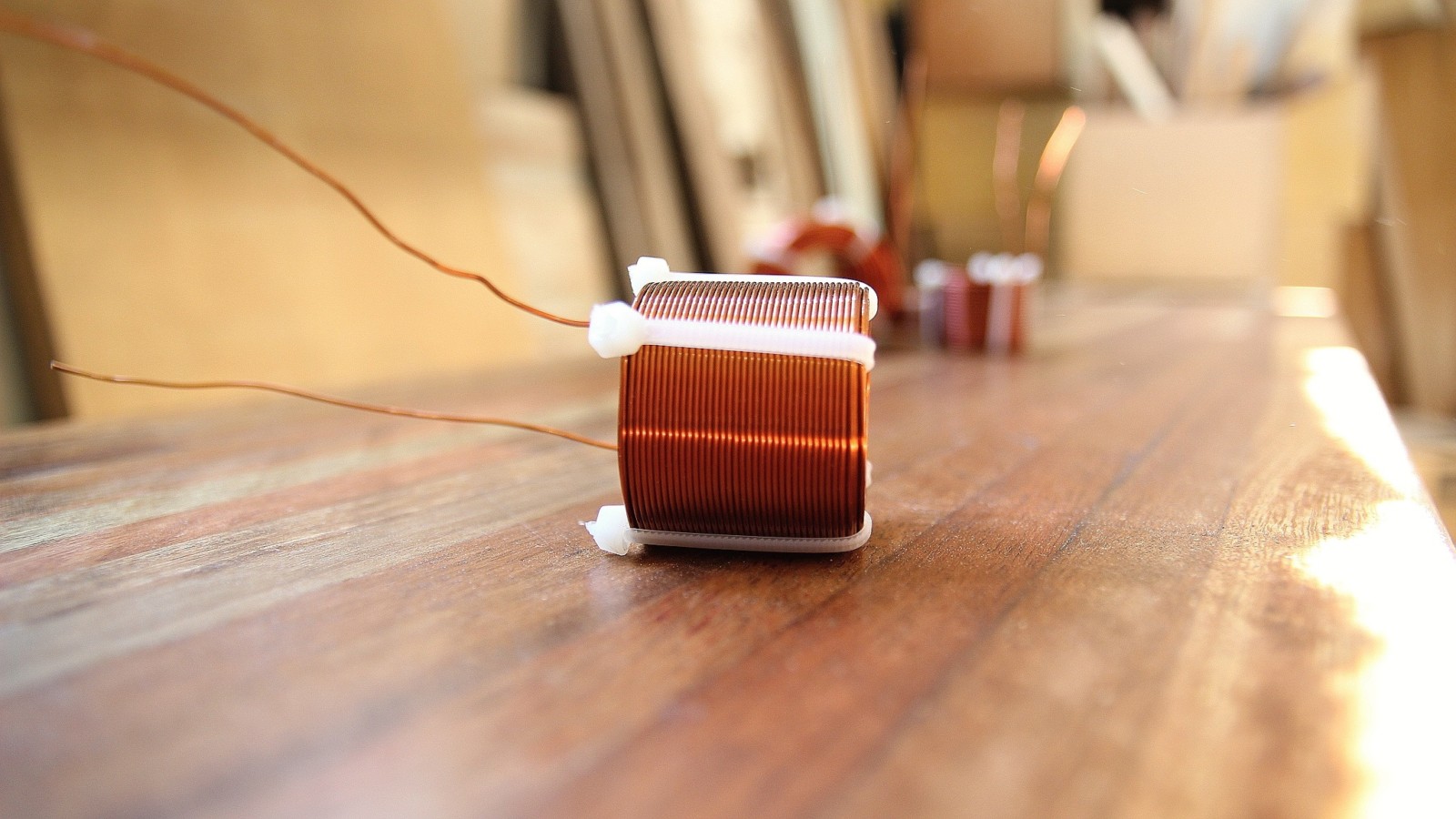
1. The acrylic sides, nice to see the windings.
2. The hexagonal shape.
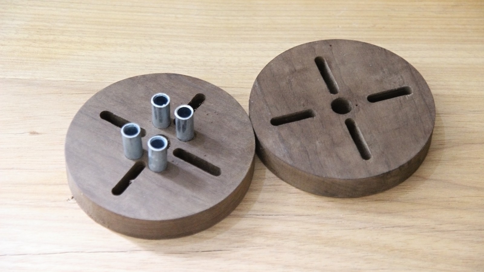
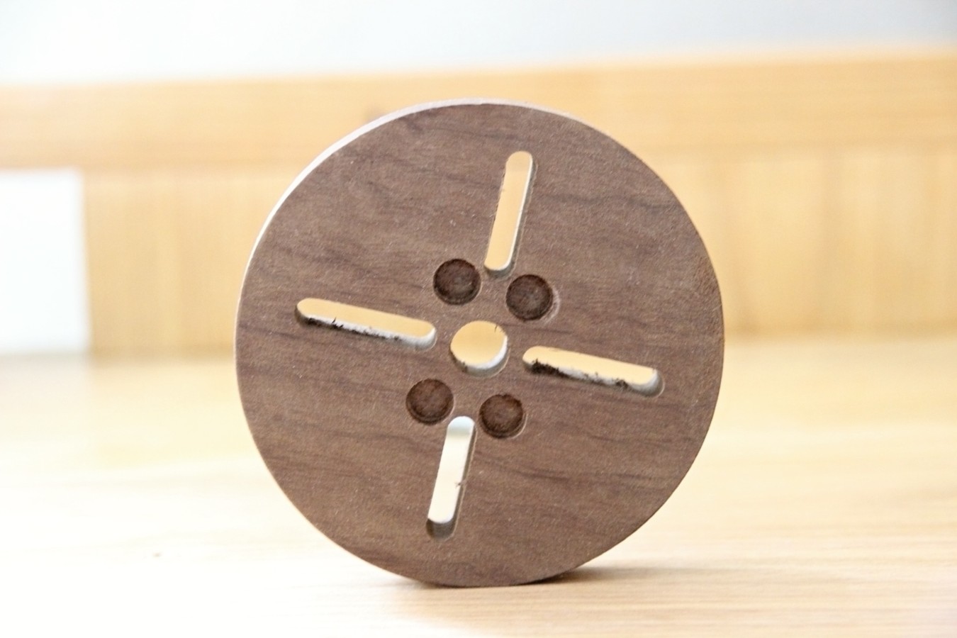
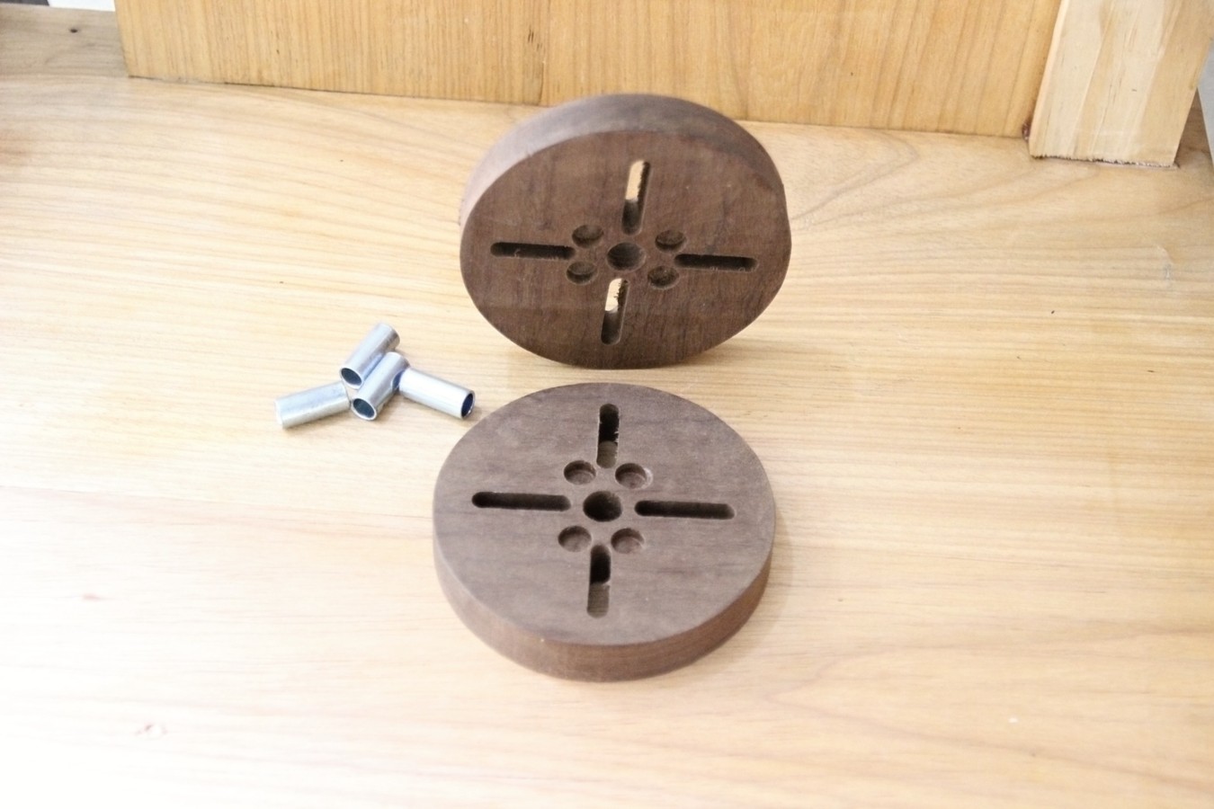
3. The slots for putting the wire ties in.
4. The way you use the sleeve gap for the starting wire.
Truly excellent work.
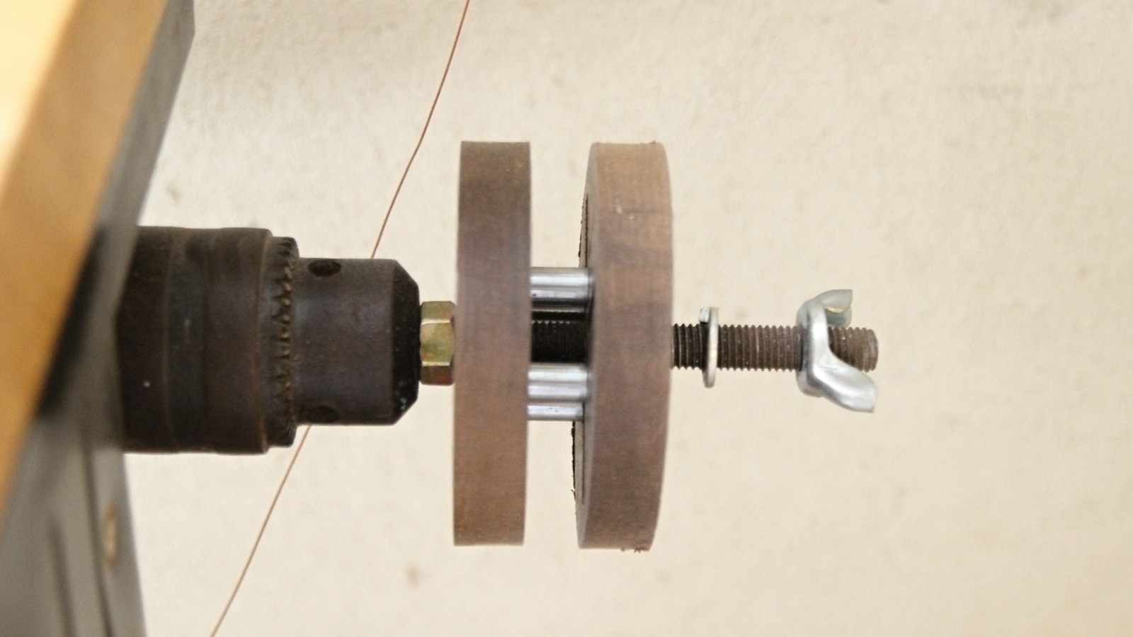
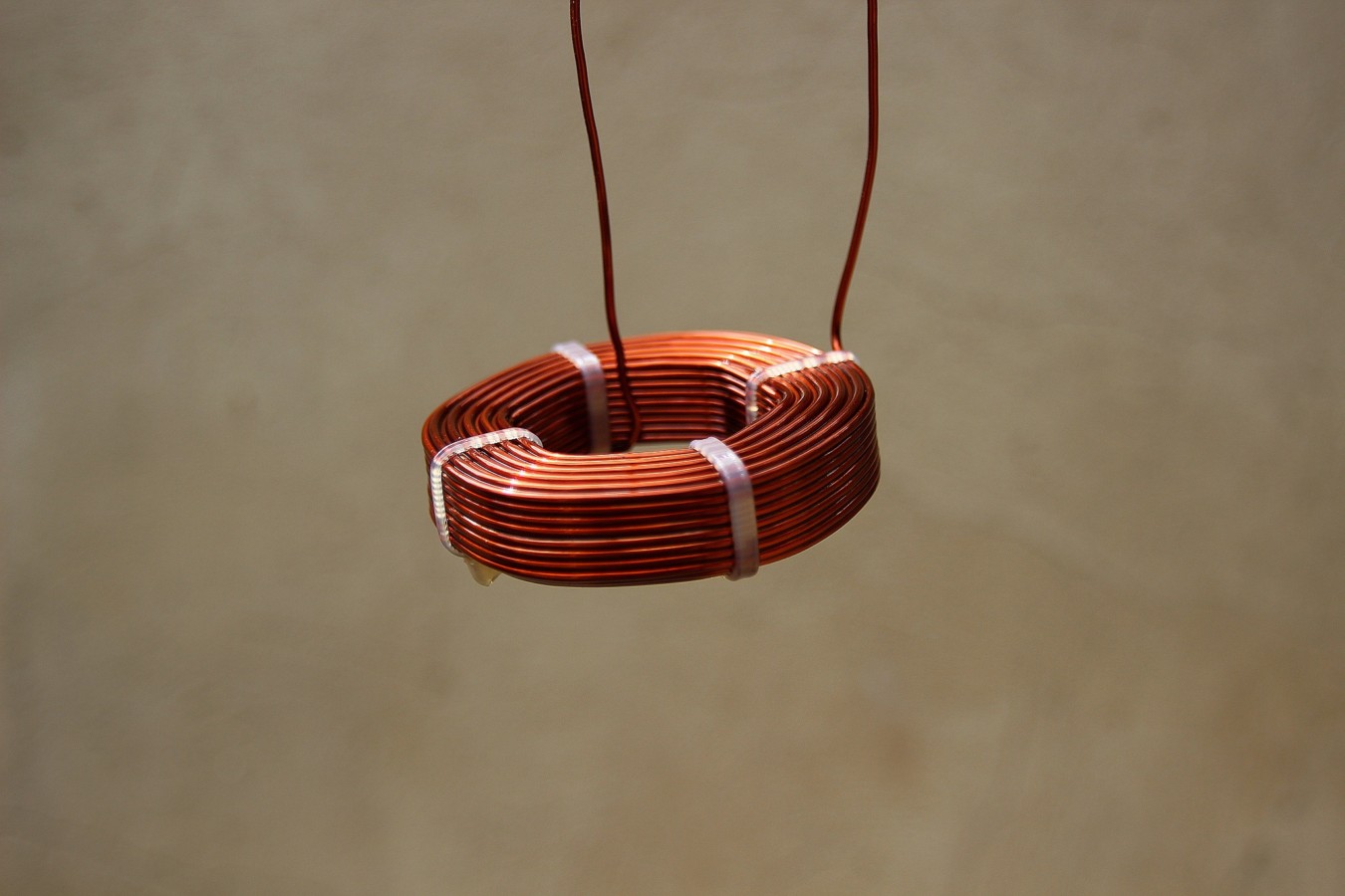
If you switched the threaded rod to an acrylic one, and used acrylic sleeves for supporting the ID (can't see if they are or not), you could actually measure the inductance in situ by using a single edge blade to nick the insulation. You'd need to keep metal at least 5 diameters from the coil.
John
1. The acrylic sides, nice to see the windings.
2. The hexagonal shape.
3. The slots for putting the wire ties in.
4. The way you use the sleeve gap for the starting wire.
Truly excellent work.
If you switched the threaded rod to an acrylic one, and used acrylic sleeves for supporting the ID (can't see if they are or not), you could actually measure the inductance in situ by using a single edge blade to nick the insulation. You'd need to keep metal at least 5 diameters from the coil.
John
Dear,
I'm sorry for not being fluent in English, but I'll try to answer everyone .. 🙂
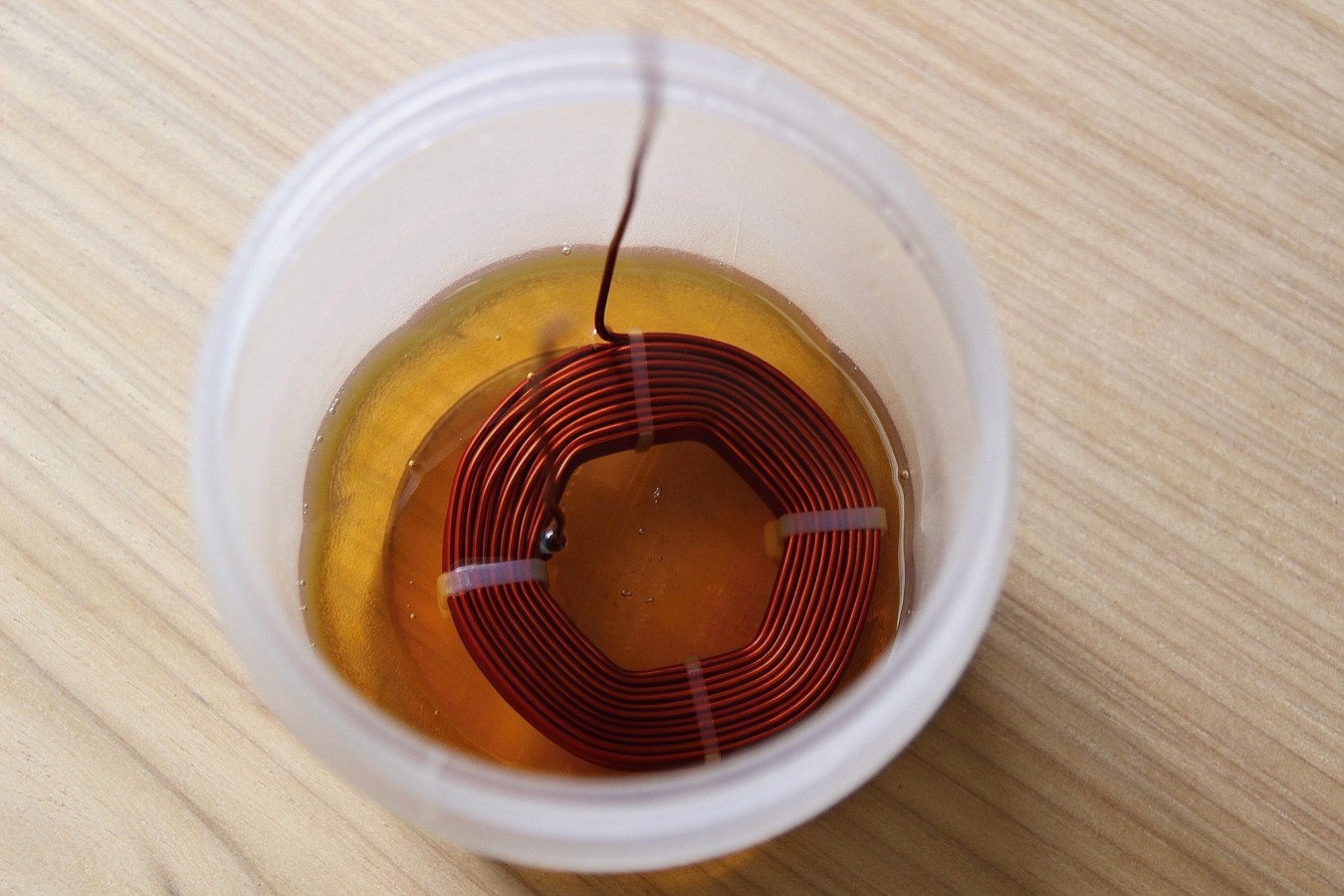
- I used the acrylic because it was a harder material than the wood, which was being deformed.
- A hexagonal model was the most efficient of all that I tested and facilitated in the way I could implement.
- To be able to measure still in the machine would be a great differential ... but after testing many software I was able to establish some criteria that allow me to make inductors with a margin of error of maximum 2% of variation.
- Coil32 - the coil inductance calculator
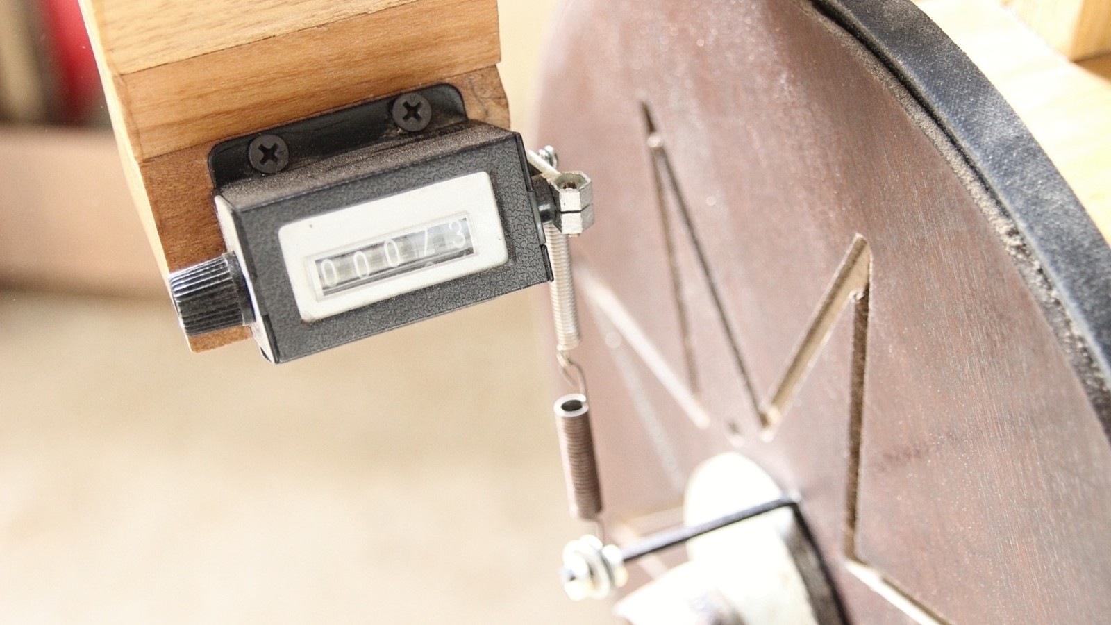
- Soon I will be upgrading the counting system, I will use this solution here:
AC or DC counter with alarm buzzer adjustable photoelectric switch sensor 10 30cm-in Counters from Tools on Aliexpress.com | Alibaba Group
- And to my mind, the understanding of this here was fundamental to the realization of this machine with excellent results.
YouTube
I'm sorry for not being fluent in English, but I'll try to answer everyone .. 🙂
- I used the acrylic because it was a harder material than the wood, which was being deformed.
- A hexagonal model was the most efficient of all that I tested and facilitated in the way I could implement.
- To be able to measure still in the machine would be a great differential ... but after testing many software I was able to establish some criteria that allow me to make inductors with a margin of error of maximum 2% of variation.
- Coil32 - the coil inductance calculator
- Soon I will be upgrading the counting system, I will use this solution here:
AC or DC counter with alarm buzzer adjustable photoelectric switch sensor 10 30cm-in Counters from Tools on Aliexpress.com | Alibaba Group
- And to my mind, the understanding of this here was fundamental to the realization of this machine with excellent results.
YouTube

- Status
- Not open for further replies.
- Home
- Design & Build
- Equipment & Tools
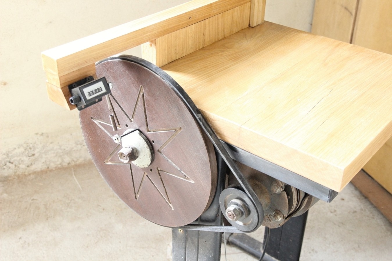
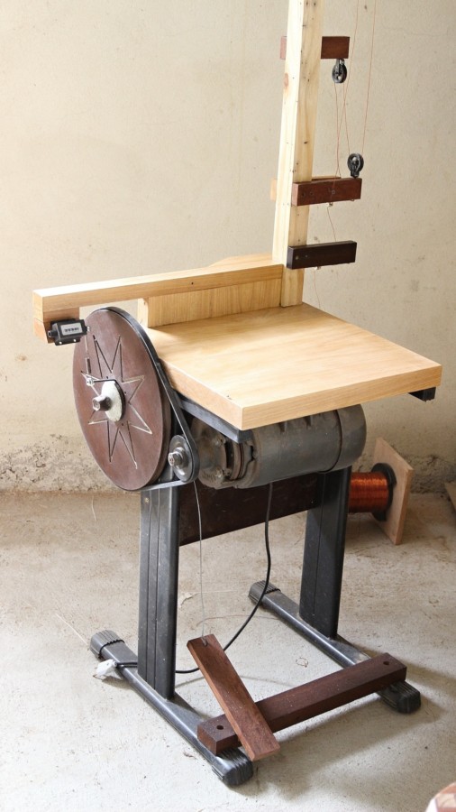
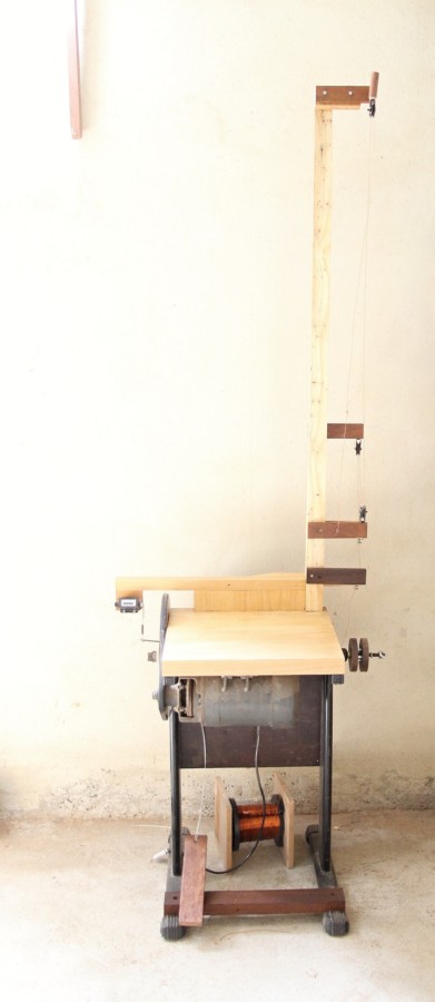
- My rustic winding machine (DIY)