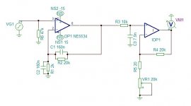
Hi all, I am new to the forums here, but i have been hiding away behind the scenes for a while. I have a bit of experience building stompboxes and Mic pre's and now i have decided to build myself a phono preamp, eventually it will be transformer balanced output to feed a pair of active speakers so i was just looking to post a schematic of the RIAA curve that i have drawn up, so that someone could have a look at it to tell me if it is right, or close.
several notes of the drawing. I will not be using an NE5534 in the end, it will probably be a JH990 running at +-24v
The Gain pot VR1 will be a 24 position rotary switch,
any tricky values for caps will be obtained by parrallaing values.
it would be great to get some feed back on this.
many thanks in advance.
P.S before someone says there are already existing designs that i could copy, the idea is to learn something, i did enough copying other peoples work at school.
Attachments

I've put this in Analogue Source as it seemed more appropriate 🙂
Now Vinyl isn't really my thing but one thing that stands out is C1 and C2 as these are effectively shorting the opamp output at AC. Have you simulated this ?
Now Vinyl isn't really my thing but one thing that stands out is C1 and C2 as these are effectively shorting the opamp output at AC. Have you simulated this ?
Yes, I simulated it in Tina spice and that is the frequency response that I got. C2,R1 acts at the stop for the 500.5hz point.
I have changed both C1 and C2 to 1.589
I have changed both C1 and C2 to 1.589
The feedback network won't work I'm afraid. You don't have a controlled high frequency gain.
Thanks for the feedback, do you mean a cap in parralal with R2R4?
It's invariably a bad idea to control gain by controlling feedback unless only a small trim is needed, say for an internal calibration. As you change gain, what was stable can become unstable and the closed loop frequency response will change. Not that it won't work, but IMO it's bad design practice as a level control. Add a buffered control or do the passive preamp thing with a medium low value pot on the output- not ideal on paper but works very well in practice.
- Status
- Not open for further replies.