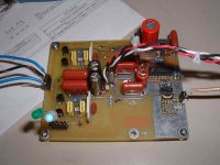
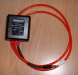
Hi. Here one of my current project. A small none-oversampling DAC using the 1545 DAC and CS8414 receiver. It is running on battery and has class-A op-amp outputs, local regulators and BG caps.
It has Scientific Conversion high bandwidth dual primaries transformer. This transfo offer the 110 ohms AES/EBU and 75 ohms SPDIF dual inputs.
I did 2 versions of PCB. The second version has balanced outputs in addition to single-ended. It is using the BB DRV134 IC's for balanced conversion. The second version is also using 4 batteries for full dual mono power supply.
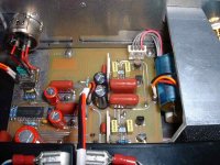
Here the version 1 PCB. It is using AN8005 SMD regulators.
It has Scientific Conversion high bandwidth dual primaries transformer. This transfo offer the 110 ohms AES/EBU and 75 ohms SPDIF dual inputs.
I did 2 versions of PCB. The second version has balanced outputs in addition to single-ended. It is using the BB DRV134 IC's for balanced conversion. The second version is also using 4 batteries for full dual mono power supply.
Here the version 1 PCB. It is using AN8005 SMD regulators.
Attachments
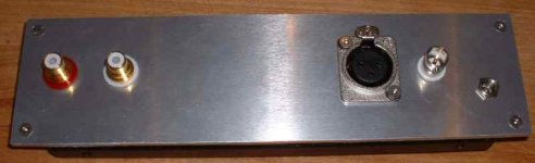
I'm building the enclosure for the version 1. Here the back panel.
It has the battery charger input connector, the AES/EBU Neutrik and true 75 ohms Amphenol insulated BNC digital inputs and Cardas RCA audio outputs connectors.
They are mounted on 1/8" alu plate.
It has the battery charger input connector, the AES/EBU Neutrik and true 75 ohms Amphenol insulated BNC digital inputs and Cardas RCA audio outputs connectors.
They are mounted on 1/8" alu plate.
Attachments
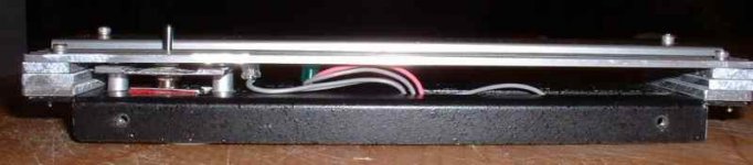
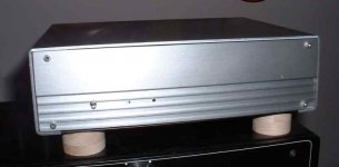
The front panel that I just completed. It is a double plates construction (I'm using a recycled very nice and strong alu enclosure). Using this assembly, I was able to hide most of the drill holes and mounting hardware, only showing 4 nice little stainless steel hex screws.
The Front plate is from a nice aluminium Hayes modem casing. It is already anodized and well finished and the grooves give some look. I used the same trick for the faceplate of my Aleph30.
We can see the power switch (On-Off-Charge) and the two leds, Power On (Blue) and Sync (Green). The leds are recessed and shown throught small pin holes. We see only a small slot for the switch.
Not too bad I think 😀
Attachments

Cannot open the file
Hi, I cannot open the file as it seems not to be a valid Winzip file.

Algar_emi said:It is a collection of differents ideas, some from the dAck! DAC, some from the Scientific Conversion white papers and some articles on the net. PCB desing are from me.
Here a summary of the features and specs.
Hi, I cannot open the file as it seems not to be a valid Winzip file.
Windoz huh......jean-paul said:It is a plain text file. I have no trouble opening it.
This file has a zip extension so this stupid PC tries Winzip.......
🙄
It had no file extension when I tried downloading, so I just gave it a .txt extension -- I assumed that's what he'd be sending 🙂
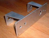
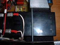
I had to find a way to hold the two batteries inside. Using some other alu bracket that I had in stock, I came up with this kind of structure.
The two brakets will be fixed to the rear and bottom of the case. They will hold the batteries and add strenght to the back and front of the enclosure. You'll see what I mean in the next images.
The two brakets will be fixed to the rear and bottom of the case. They will hold the batteries and add strenght to the back and front of the enclosure. You'll see what I mean in the next images.
Attachments
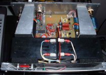
This is a zoom of the installed PCB. The power is coming in the middle, mdiway between all needed supplies.
On the top left corner are the SPDIF and AES/EBU inputs, close to the digital transformer.
On the top right are the leds outputs.
On the right are the audio outputs, very close to the coupling caps.
On the top left corner are the SPDIF and AES/EBU inputs, close to the digital transformer.
On the top right are the leds outputs.
On the right are the audio outputs, very close to the coupling caps.
Attachments
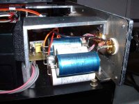
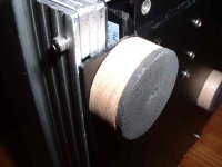
These are the current coupling caps I'm listening to. They are CDET Cornell Dubilier) 2.5uF-630V+ 2.0uF-100V (1% cap!) + ERO1832 0.047uF-250V.
They are just a bunch of surplus caps that I'm trying waiting to have some money to spend on some nice Mundrof M-Cap 3.3uF.
The sound is better that some 5uF AuriCap caps I tried.
We can see the foam that stabilize the battery and some more details of the bracket.
They are just a bunch of surplus caps that I'm trying waiting to have some money to spend on some nice Mundrof M-Cap 3.3uF.
The sound is better that some 5uF AuriCap caps I tried.
We can see the foam that stabilize the battery and some more details of the bracket.
Attachments

- Status
- Not open for further replies.
- Home
- Source & Line
- Digital Source
- My new 1545-cs8414 nos DAC