Hi all
Firs of all thanks to all the gays here that help me so much to build this amp.
This is the best sound I hear ever !
The circuit is so simple, this is masterpiece.
I have a lot of mistake in this pcb, all the time the 2sk/j burn me and I don’t know way.
After I replace 5 from the 2sk and 5 irf that I burn I decide to Retire, and I buy some chip amp kit on eBay. Then I find my mistake:
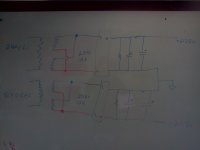
My PS including 2 transformer, one for + and one for -.
The thing is that I power on the + and then the – because if I turn both of them together I burn the fuse.
Another mistake is that the + was 33vdc and the – was 29vdc.
I think this is the problem because the new kit from eBay burn too.
After change back to regular PS: one transformer and one power button the amp works!
So I think I back to the F5.
Thanks to everyone here.
erez
Firs of all thanks to all the gays here that help me so much to build this amp.
This is the best sound I hear ever !
The circuit is so simple, this is masterpiece.
I have a lot of mistake in this pcb, all the time the 2sk/j burn me and I don’t know way.
After I replace 5 from the 2sk and 5 irf that I burn I decide to Retire, and I buy some chip amp kit on eBay. Then I find my mistake:
My PS including 2 transformer, one for + and one for -.
The thing is that I power on the + and then the – because if I turn both of them together I burn the fuse.
Another mistake is that the + was 33vdc and the – was 29vdc.
I think this is the problem because the new kit from eBay burn too.
After change back to regular PS: one transformer and one power button the amp works!
So I think I back to the F5.
Thanks to everyone here.
erez
Last edited:
Nice to see you got your working, I burned up one channel of mine by shorting it out when I was re-biasing it.
Dave
Dave
Hi
My F5 steel don’t work, I just assume this is the reason.
Even its not working, this is so simple. Just remove 4 transistor and check.
After replace my 4 transistor and check the resistance my F5 burn again, its have to be the PS.
I buy some chip transistor from eBay until the amp work normally and then I move to match pair again.
The thing is that my amp work fine after replace the semi, but when I put more volume in the input I see DC in the output.
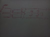
and i remove the protaction stage, so now its more simple
My F5 steel don’t work, I just assume this is the reason.
Even its not working, this is so simple. Just remove 4 transistor and check.
After replace my 4 transistor and check the resistance my F5 burn again, its have to be the PS.
I buy some chip transistor from eBay until the amp work normally and then I move to match pair again.
The thing is that my amp work fine after replace the semi, but when I put more volume in the input I see DC in the output.
and i remove the protaction stage, so now its more simple
Last edited:
33v and 29v is too high.
The power supply SHOULD be turned on so that both plus and minus starts at the same time.
The two transformers need to be *identical*.
There needs to be a connection between the two in order to create the CENTER point which is referenced (connected) to GROUND.
When you turn on the amp, you should have a light bulb (incandescent) connected in series with one of the AC mains leads. Ideally one would use a Variac (variable auto-transformer) to bring the AC power up slowly from a low voltage to full voltage. Just flipping the switch is an invitation for disaster.
The lightbulb gives some degree of protection. In your case a small lightbulb might be preferable, like 30watts or 20 watts...
Perhaps you might want to post some clear sharp images of your amplifier's internal wiring?
_-_-
never connect secondaries directly in parallel , unless you are certain that manufacturer made them for that .
connect rails in parallel after diode bridges , without harm
of course , that calls for each secondary having own diode bridge
connect rails in parallel after diode bridges , without harm
of course , that calls for each secondary having own diode bridge
that's correct
all you need is to read schematic Papa already posted , if you're already going to make project by them
all you need is to read schematic Papa already posted , if you're already going to make project by them
Pretty safe to parallel secondaries of a transformer with dual secondaries that are identically rated and spec'd by the mfr. Imo.
But 21vac in will not give 21vdc out.
You will get 1.414 x 21vac since you have a "cap input" filter on the output.
So you'd expect 29vdc - which again is too high. Very much on the edge of what you would want to run given the input devices - the outputs are fine. Probably will work ok, but you also have to account for slightly higher AC line voltages...
_-_-
hi
Few month ago when I start to build the F5 I have 2 transformer: 16ac and 21ac.
After read Mr. nelson PDF about turbo F5 I realize that I can use the 21ac with no change in the ver.2 pcb from DIY (the first F5).
So I connected the F5 to 33vdc !!
its wrong?
Maybe this is the reason for burning the F5 all the time?
Thanks all
- Status
- Not open for further replies.
- Home
- Amplifiers
- Pass Labs
- My mistake on the F5