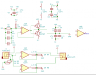
Can someone tell me what is wrong with my project (Headphone amp)? This is the schematic - https://mega.nz/file/QIUjEICC#VbKKIqi78RDFpo35uJgizh1zJOd4uxZZ5HPhsMvrtNA
There's a weird hum that's louder on one side of the earphones btw, which is weird since both sides have the same circuit. The hum goes away when I connect the amp to a source but even so, I don't understand why there's a hum in the first place since both inputs get pulled down to 0 when nothing is connected. I've tested this out on a battery as well, just to make sure that it isn't my power supply. When I do connect my amp to a source, a different hum appears that's significantly lower in volume, and it differs from source to source. Another thing to note - when I connect my smartphone to the amp, there are a lot of glitches (But only on one ear, the same one I mentioned before) and a particular glitch that can be heard for a very short period of time and will repeat a couple of times every second continues for a bit even after I disconnect my phone.
So, can someone tell me what's going wrong? Is it because of the breadboard? I've heard they're not very good for low noise applications, but I didn't know things were this bad, or is it (more likely) something else?
Lets have the circuit so we can see it 🙂
Breadboard layouts should be fine for this... noise free.
The circuit looks a bit odd. Why the 2k2 and 1k divider on the opamp outputs? That will mean any load you attach to socket J3 will just kill the signal at that point while causing the opamp to increase its output and clip. The feedback should be taken from the opamp output and you may then use a single series resistor to the load... but more like 47 ohms or so.
The TL072 is about the worst choice for a headphone amp driver stage due to its limited current delivery but even so it will still make a fair old noise (in a good way).
Attachments
Last edited:
Sorry about that 2.2K, that's a mistake. The J3 header is connected to the output of the op amp directly, not to the 2.2K. This amp isn't driving anything insane - a pair of cheap IEMs (QKZ VK4, 16R) is what I'm using right now.
Here are the pics:
Rail Splitter - https://mega.nz/file/kRMVFILC#QJlO3LoFUblziZYkwF4s-5BP2V2zH63b9_zN8ebF91E
Amp - https://mega.nz/file/ocMjnazD#OE65vzfFJ0ZkED_iL3fqkZBxWSgoSyTcEjomC3n5CZg
There is no input jack, the input is taken from the 3 pin header you see.
The rail splitter's output is connected to the inner rail on both sides on the second half of the breadboard.
No problem 🙂
The first things to check is that the DC conditions are correct and so that means zero volts DC at the opamp outputs.
Next I would add a series resistor to the headphones. Something like the 47 ohm I mentioned.
The amplifier itself can't hum in the normal sense and certainly not when battery powered. So that leaves either some external influence or the possibility the thing is unstable in some way.
So check the DC conditions and try the series feed resistor.
As you are using a virtual ground you need to be sure that the audio input ground is using the correct virtual point and not the battery negative as ground.
Thanks for the advice.
I have actually checked the DC conditions - they are quite stable from what my multimeter shows me. There are some ridiculous 50mV peaks on the ground rail (Very slow btw, About a hertz since it's clearly visible on my scope's roll mode) when I touch the input 3.5mm plug, but outside of that, from what I can tell, the rails themselves are very stable (I've gone ham with the decoupling since it was too noisy, and I did check). There is a very small DC offset on the output (10mV or so), but that shouldn't cause any issues, I don't think, and I did add some DC blocking caps, but the result remained the same (Outside of the filtering effects ofc).
I have actually checked the DC conditions - they are quite stable from what my multimeter shows me. There are some ridiculous 50mV peaks on the ground rail (Very slow btw, About a hertz since it's clearly visible on my scope's roll mode) when I touch the input 3.5mm plug, but outside of that, from what I can tell, the rails themselves are very stable (I've gone ham with the decoupling since it was too noisy, and I did check). There is a very small DC offset on the output (10mV or so), but that shouldn't cause any issues, I don't think, and I did add some DC blocking caps, but the result remained the same (Outside of the filtering effects ofc).
BTW, forgot to mention this, but as for the series resistor - the smallest value I have is 220R, and I can't buy any because COVID19 lockdowns.
The virtual ground is (or should be) your only reference point for measuring to and from and so you should not see any voltage or spikes at any ground point in the circuit.
Your scope and meter readings should all be measured from that virtual ground point.
10mv offset is low of itself but it should be much lower than that with a genuine TL072 which is a FET device and so does not suffer from input bias current effects causing offset voltages. I would have expected under a millivolt tbh.
So using the virtual ground for the grounding of the scope you should not pick up any noise or anything at all on any ground point in the amp because they are all of course the same point.
Check the plus and minus rails with the scope still measuring from the virtual ground. They should be clean.
If you have doubts over the input connections and wonder if they are picking anything up then try shorting out R1 and R3. That will tie the + inputs direct to virtual ground and the amp should be dead silent in that condition with all DC conditions correct.
I'll look in again tomorrow 🙂
BTW, forgot to mention this, but as for the series resistor - the smallest value I have is 220R, and I can't buy any because COVID19 lockdowns.
220 ohm is fine as a test value. Many headphones will still go pretty loud even with that in series.
Firstly the virtual ground arrangement with those class-B transistors is bad, add a 1k resistor from IC1a's output to the ground - without this it may have been oscillating wildly. You need to ensure the feedback look is closed at all times.
Secondly the TL072 cannot drive headphones by itself, not enough current.
Thirdly opamps cannot drive cables directly, as the capacitance may send them into oscillation - add a small resistor between the output connector and the thing driving it.
The class B transistor buffer circuit you've used, if done properly, can boost an opamp's output so it can drive headphones - use perhaps 30 ohms of output resistance to stabilize it.
A dedicated current buffer chip is another option for beefing up the output of an opamp.
10k resistors to ground on the inputs will not stop hum pickup, but will reduce it substantially compared to 50k resistors at least...
A breadboard circuit will pick up some hum anyway, its not in a metal box. Yes it is that bad - partly because headphones are very efficient at allowing you to hear a few microwatts of signal.
After another look, the GND rail is not stable (And I have no idea why, I've decoupled the reference as well as the output quite well, with one electrolytic and one ceramic on both, with the reference having a film big 1u film cap as well. It's being driven by a push pull output stage with fairly high current transistors too). It does jump around. And something even more interesting - the unused op amp on the TL072 used for rail splitting seems to be causing issues - touching the output of the unused op amp (and only that) seems to cause a significant decrease in noise (It's very faintly audible, but that's it), but the glitches I mentioned didn't go away. I did try shorting the input leads to gnd btw, and yes the op amp was dead silent. Also keep in mind that the offset I mentioned may not be accurate - it was measured by a terrible meter and my scope (the DS1054Z) does have issues with a slightly inaccurate offset IIRC.
Thank you for the help.
Thank you for the help.
your ground rail only needs a 220 ohm resistor to the TL074 and (+) pin of 1 470uf cap to ground.
the cap to the power rail is the problem. The AC current from the output op amps will flow through the capacitor. TL074 has only 10ma or so of output current and it is not balanced, so the clipping is weird.
the cap to the power rail is the problem. The AC current from the output op amps will flow through the capacitor. TL074 has only 10ma or so of output current and it is not balanced, so the clipping is weird.
@Mark Tilltotson
Why does adding a 1K resistor to ground change the issue with oscillation? Since there are no phase shifts or inversions, why would the output of the rail splitter be unstable? I can see the op amp's output oscillating to accommodate for the small changes in voltage on the rail, but that's what the output of the op amp is supposed to do, and in doing so the output of the push pull stage remains at 0V.
I was actually planning on using a class B stage after the op amp stage as you suggested, but unfortunately that circuit exaggerated the noise even more (It wasn't crossover distortion - the output of the stage was in the feedback loop).
However I would like to know why putting a 220R in series with the earphones, as Mooly suggested, suddenly stopped the hum (Not the glitches, those still occur). Distortion due to the emitter resistance being as or more dominant as the 16R load would be the first thing to come to my mind, but of course, at no input that shouldn't really matter any way.
@stocktrader200
Can you explain in more detail? Yes, true, the cap to the power rails can cause coupling from the positive rail, but the positive rail itself is very well decoupled with the negative rail, can it still be significant? Unfortunately, at the 10ish mV range (which is what I'm having to deal with right now), my tools are not really good enough (Mostly my meter, which is a cheapie), so I can't actually test it.
Can you explain in more detail? Yes, true, the cap to the power rails can cause coupling from the positive rail, but the positive rail itself is very well decoupled with the negative rail, can it still be significant? Unfortunately, at the 10ish mV range (which is what I'm having to deal with right now), my tools are not really good enough (Mostly my meter, which is a cheapie), so I can't actually test it.
However I would like to know why putting a 220R in series with the earphones, as Mooly suggested, suddenly stopped the hum (Not the glitches, those still occur).
It is all a matter of piecing all the evidence together 🙂
At the beginning I mentioned:
The amplifier itself can't hum in the normal sense and certainly not when battery powered. So that leaves either some external influence or the possibility the thing is unstable in some way.
The series output resistor dramatically aids stability of the opamp which may be objecting to the low impedance load of the headphones and cable and causing it to do funny things. Even a few ohms can be enough to stop this.
I'm still puzzled by you saying the ground lead is not stable... which may sound like a play on words but its important because ground is your reference point and so if anything is unstable it is happening relative to ground.
The rails may be altering relative to ground but ground can't alter because it is your chosen reference point. It is fixed and unchanging.
Which leads on to Mark's point of the resistor...
The class B pair have a dead band needing a base voltage of around +0.6 volts for the upper device to conduct or -0.6 volts for the lower device to conduct (relative to our ground 😉).
If the amp draws an unbalanced current from the rails (so more from one rail than the other) then the opamp output will turn on the appropriate transistor to allow that current to flow.
The problem is if the current draw is essentially equal for both and the opamp output is hovering at some really low voltage with neither one or the other transistor conducting. Now the opamp is making constant corrections jumping between 0.6 and -0.6 to try and maintain equilibrium.
A resistor between B and E of the pair actually allows the opamp itself to supply the minute changes needed directly without even needing the transistors. So a potential source of low level instability is removed.
It must be said however that such instability can not alter the ground line, only things around it for the simple reason ground must be your absolute reference. Everything moves around ground and not ground itself moving.
And... you say it was silent when you linked the inputs to this unmoving ground as I suggested. That shows that something is possibly being picked up on the input side of things.
@Mooly
> The series output resistor dramatically aids stability of the opamp which may be objecting to the low impedance load of the headphones and cable and causing it to do funny things. Even a few ohms can be enough to stop this.
Could you elaborate on that a bit more? Is the headphone cable behaving like a transmission line and causing phase shifts to cause instabiity? Either way, why does adding only a few ohms make much of a difference? The op amp itself has an output resistance of around 150R, wouldn't this take care of the instability? Why do we need another resistor in series with the load that is insignificant compared to the output resistance? How does that stabilize the op amp?
Sorry about all this, I realize I can be a bit annoying with so many questions, but hey, a man's gotta learn.
Thank you
The headphone cable is an 'unknown' but will be guaranteed to posses some self capacitance. Different opamps handle this capacitance appearing across the output in different ways, anything from total and obvious instability to just a subtle 'thickening' of the scope trace indicating something is going on at very high frequency.
All opamps have some output resistance (but not 150 ohm 😉) and this resistance adds another pole to the overall transfer function, the result of which can be instability depending on the open loop gain and feedback wrap around of the circuit.
So this 150 ohm... the TL07x series have a series output resistor which the current data sheet shows as 128 ohm. There are also some pretty large emitter resistors in the output stage but the output impedance of the opamp as far as we are concerned is but a fraction of an ohm because that 128 ohm resistor is internal to the circuit and so inside of the feedback loop.
When we use the opamp and add feedback we see an output impedance that is extremely low indeed as measured at the feedback take off point.
Attachments

Last edited:
Because you have the transistors operating in class-C - they are not biased to conduction at the mid-point, they are in cutoff. Adding a resistor allows the feedback loop to be closed during this "gap" in the response. With a proper class-B buffer stage both transistors would be slightly conducting at the midpoint so that the feedback loop is still closed and the opamp's output doesn't have to sudden jump a gap.@Mark Tilltotson
Why does adding a 1K resistor to ground change the issue with oscillation? Since there are no phase shifts or inversions, why would the output of the rail splitter be unstable?
What your circuit has is more like current-dumping but without the straight-through resistor I mentioned. 1k was a total guess BTW.
It was a combination of oscillation and crossover distortion I reckon.I can see the op amp's output oscillating to accommodate for the small changes in voltage on the rail, but that's what the output of the op amp is supposed to do, and in doing so the output of the push pull stage remains at 0V.
I was actually planning on using a class B stage after the op amp stage as you suggested, but unfortunately that circuit exaggerated the noise even more (It wasn't crossover distortion - the output of the stage was in the feedback loop).
Once a circuit oscillates at HF its audio performance can drop radiacally, including PSRR, thus allowing supply hum to appear, as well as distortion and noise.However I would like to know why putting a 220R in series with the earphones, as Mooly suggested, suddenly stopped the hum (Not the glitches, those still occur). Distortion due to the emitter resistance being as or more dominant as the 16R load would be the first thing to come to my mind, but of course, at no input that shouldn't really matter any way.
This page might give some ideas for better class-B transistor buffers: https://www.electronics-tutorials.ws/amplifier/amp_6.html
And I found this one talking about current dumping, you'll see the straight-through resistor in the first image: Current Dumping Article
There are also opamps with a high output current ability that would avoid having to have a buffer circuit - although finding one with good audio performance might be tricky.
- Home
- Amplifiers
- Headphone Systems
- My "headphone amp" is very noisy. How do I fix it?