Hi all,
I am in the finishing stages of my first point to point project. It is from Vacuum Tube Valley issue number 11. I ran across the thread by jdrouin where he did this build and it seemed like a good one to try out the point to point build.
Please, any critique or advice on how to improve will be greatly appreciated.
Attachments
Hmmm... not sure, I'll try again later...Your attached schematics are only 5kb in size. What happened?
jeff
resized schematics
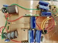
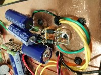
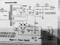
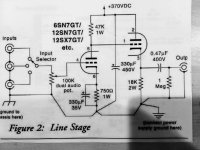
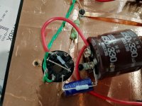
Here are the resized schematics plus another view of the build.
Here are the resized schematics plus another view of the build.
Attachments
Last edited:
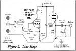
Try it without the cathode bypass cap.
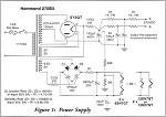
Use an indirectly heated rectifier so that the heater voltage has time to come up to potential before the plate voltage (Type 5V4).
Reduce the local 330uF to 10uF and use a film capacitor.
If you are using 6SN7, replace the heater circuit with LT1085 type as a current regulator, 2x 270k across the output as a faux CT and use this node to elevate the winding. Oh, .. and use four diodes for rectification.
Last edited:
In other words, start over... lol I already have the 5V4 for the rectifier. What will be the effect by changing the 330uF …. I looked for a film cap when I was buying them (I've read enough to know that is the recommended audio cap) but couldn't find the 330 @ 450V in anything but electrolytic.
I put the heater power supply circuit on the scope and it reads clean and steady so unless it sounds like crapola I'm going to leave that as is 🙂
I put the heater power supply circuit on the scope and it reads clean and steady so unless it sounds like crapola I'm going to leave that as is 🙂
My main thing is to try to avoid smoke. 😱 I have my variac to start it up, so unless someone spots a grievous error I'll probably do like you say and give it a listen.
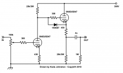
Agreed, 330uF is larger than needed. I would use 22uF or 47uF. Also, add a diode from second grid to second cathode to prevent the tube from being destroyed (When the tube is cold and not conducting, the grid will be at B+, the cathode at ground. Not good. When the tubes warm up and conduct, the diode "falls out" of the circuit, being reverse biased). Also check the DC coupling voltages are right. It looks off to me. I've drawn my version for you. Your version will work fine if you capacitor couple the stages. I've left the PS RC filter off of this diagram.
Cheers.
Cheers.
Attachments
Agreed, 330uF is larger than needed. I would use 22uF or 47uF. Also, add a diode from second grid to second cathode to prevent the tube from being destroyed (When the tube is cold and not conducting, the grid will be at B+, the cathode at ground. Not good. When the tubes warm up and conduct, the diode "falls out" of the circuit, being reverse biased). Also check the DC coupling voltages are right. It looks off to me. I've drawn my version for you. Your version will work fine if you capacitor couple the stages. I've left the PS RC filter off of this diagram.
Cheers.
Thanks, I definitely don't want to fry tubes or anything else for that matter ….
- Status
- Not open for further replies.
- Home
- Amplifiers
- Tubes / Valves
- My first point to point, a 6SN7 Line Stage