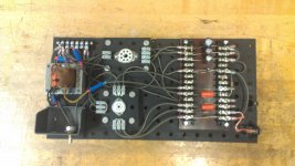
Been playing with my first amp build! Was the previous "squealing" clone, but shielding every thing from the input to the 2nd preamp stage grid & got rid of almost all of it. All components are per schematic (so far), and have been subbing preamp tube (for 12AT7 and 12AU7). Putting in a 500Hz sine wave (and then guitar), and looking at it on my scope, with either a 4ohm spkr or dummy resistor on the OT. Recording all B+ and tube voltages for each test. Questions:
1. Noticed lower plate DC voltages using an AT7 or AU7. Being lower mu tubes, and seeing lower signal (AC) voltages (pin 6), I would think tube current would be lower (meaning a higher "tube resistance"?), and would make the plate voltage HIGHER???
2. I also saw clipping on only half the sine wave - is this Asymetrical clipping? Is this desireable? Sounded good with guitar and speaker. Why only half the sine wave?
3. Using a speaker causes oscillations that I don't see when using the dummy load (I can see them modulating the sig gen sine wave). And only at low vol (it growls) and hi vol (sounds like feedback) but clean at midrange. Any suggestions or explanations?
Thanks for reading and ideas (in advance!).
Attachments
What determines the plate voltage on the 12AX7? The current through the 100k plate resistor. Those other tubes may not have as much signal gain as your 12AX7, but that is not the same thing as DC current through the tube. Those tubes are conducting more. Consider zero signal, as in none applied or just a space between notes of music. There would be nothing for gain to amplify, yet the tube still conducts.
There are two limits to tube conduction. If the signal or voltage at the grid goes too far negative, the tube goes into cutoff - the electrons cannot get past the grid. On the other extreme, if the grid goes positive with respect to cathode, the grid starts to draw current.
Your preamp stages have 1500 ohm cathode resistors. The current through the 12AX7 triodes causes a voltage drop across those resistors. Typically that is a volt or so. That volt or so is your bias voltage for the triode. The cathode is a volt more positive than the grid. That is the same as the grid being a volt more negative than the cathode. Your signal comes into the grid as an AC voltage - a voltage swinging from positive to negative and back. When the peaks go negative, they pinch the tube conduction off more and more until cutoff is reached. When the peaks go positive, once they reach that volt or so level, they then pass the bias and any further increase causes grid current. That happens at your volt, the cutoff takes more than that, so your signal is clipped unevenly. Desirable? Up to you.
3. I am not sure what you are reporting. Tubes can be microphonic, tap on them while it is running to see. You might have parasitic oscillations. Breadboarding is convenient and fun, but it is a less than optimal layout for a gain circuit. A lot of excess wire length and wires positioned near other things. And you might disconnect the negative feedback wire to see if that is involved - you might have the output transformer wires backwards.
- Status
- Not open for further replies.