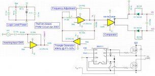
So I have had this project kicking around in my head for about a year now, but finally it is looking like it will become a reality. Back in January I drew up this schematic and I even got a prototype PCB made (since I was ordering a lot of other boards at that time). I never got around to building it. Before I spend all the time/money on the last few parts and building this thing does it look like it will work?
One concern I have is the finally output stage, the IR2011 (wired up as in the data sheet) is operating on a single supply, but wont this limit the range of the speaker? How can I get around this? Is there a better driver out there that will allow me to use a split supply (I have a nice +/- 30V one ready to go).
One concern I have is the finally output stage, the IR2011 (wired up as in the data sheet) is operating on a single supply, but wont this limit the range of the speaker? How can I get around this? Is there a better driver out there that will allow me to use a split supply (I have a nice +/- 30V one ready to go).
Attachments
You'll blow out the driver if you run it straight from a half bridge because the AC signal will be based around half of your rail voltage (15v). You either need to use a full bridge or use a filtering series capacitor. You should also have an LC filter before the signal leaves the amp chassis.
50kHz is too low unless you're only driving a subwoofer.
Using OPA134 to generator a triangle wave is a waste. Use a TL072 or something. There are other things but I didn't look really closely at your circuit. It's not a bad start, you're understanding the concepts.
--
Martin K
50kHz is too low unless you're only driving a subwoofer.
Using OPA134 to generator a triangle wave is a waste. Use a TL072 or something. There are other things but I didn't look really closely at your circuit. It's not a bad start, you're understanding the concepts.
--
Martin K
The circuit you pasted from the IR2011 datasheet is really generic. For the half bridge you would drive the high and low with the same signal ( I think one of the inputs is inverted on chip )
The only reason you would run separate PWM into the IR2011 is if you are doing phase shifting, which you are not. I don't really understand what you're trying to accomplish with your comparator outputs..
The analog audio input should be filtered to prevent any audio signals over 1/2* Fsw.
The MOSFET gates should be run at 12v unless you're using logic level FETs...
Thanks for the reply, this has been very helpful! I did not realize that one of the inputs on the IR2011 was inverted that is why I was using that comparator. For the output LC filter how do I size the inductor?
P.S.
This amp will be used purely for a subwoofer @ less than 120hz
P.S.
This amp will be used purely for a subwoofer @ less than 120hz
Can anyone confirm that one of the inputs on the IR2011 is inverted? I have found no other mention about this and looking at some other amp schematics on the net leads me to think that is not correct.
Here is my new schematic, what do you all think? I have simulated it using opamps instead of the twin IR2011 drivers (using TI-TINA does not allow the IR2011) and it looked ok to me.
Here is my new schematic, what do you all think? I have simulated it using opamps instead of the twin IR2011 drivers (using TI-TINA does not allow the IR2011) and it looked ok to me.
Attachments
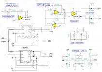
It looks like it would work. What you should do is start at a lower voltage and a lower frequency (12v and 10kHz) and ramp up the frequency and power from there.
The diodes in the IR2011 drivers must be rated for at least 50v and should be schottky or very fast recovery.
The Vb-Vs capacitor should be at least 10 times the Cgs capacitance of the MOSFET. I usually use 1uF ceramic caps.
The Vcc caps on the IR2011 should be at least a few uF ceramic as well. Keep every trace having to do with the gate drive as short as possible.
I like to put 15v zener diodes from the gate to source of the MOSFETs to try to circumvent spikes.
I'm not sure if you will be able to drive your MOSFETs up to 200kHz with those gate drivers. They don't sink very much current. I would use 10 ohm gate resistor to start and you will probably end up wanting to put ferrite beads on the FET gate pins to get cleaner switching waveform.
Good luck!
raidfibre said:It looks like it would work. What you should do is start at a lower voltage and a lower frequency (12v and 10kHz) and ramp up the frequency and power from there.
The diodes in the IR2011 drivers must be rated for at least 50v and should be schottky or very fast recovery.
The Vb-Vs capacitor should be at least 10 times the Cgs capacitance of the MOSFET. I usually use 1uF ceramic caps.
The Vcc caps on the IR2011 should be at least a few uF ceramic as well. Keep every trace having to do with the gate drive as short as possible.
I like to put 15v zener diodes from the gate to source of the MOSFETs to try to circumvent spikes.
I'm not sure if you will be able to drive your MOSFETs up to 200kHz with those gate drivers. They don't sink very much current. I would use 10 ohm gate resistor to start and you will probably end up wanting to put ferrite beads on the FET gate pins to get cleaner switching waveform.
Good luck!
Thanks for your comments. I will do as you say and slowly ramp up the frequency and the power while watching it on my scope. If 200khz does not work 100KHZ should be ok since this is only going to be a bass amp. Cheers!
P.S.
I am a mechanical engineer by education/trade; I have worked with plenty of simple electronics but this is the first “complex” system I have tried to design.
thefish can u supply me with a schematic of your design. My email is kyu333@gmail.com. thanks and good luck with your project
Hello everyone I'm working on a triangle generator for a class D amplifier so far I tried the LM566(discontinued) and the NTE994m(discontinued) now this two are gone and I can't get anything that will work. I have tried the 8038 bt I cant get the 180Khz to 200Khz that I desired. Does anyone know what other options are out there?
I'm trying to get 2.5 amplitude. I can get a 10khz but when I design for the desired It will give me like 130K instead of 180-200K
maverick_123 said:thefish can u supply me with a schematic of your design. My email is kyu333@gmail.com. thanks and good luck with your project
Sorry for the late reply, but the schematic attached to my post shows the triange generator I am using.
maverick_123 said:Hello everyone I'm working on a triangle generator for a class D amplifier so far I tried the LM566(discontinued) and the NTE994m(discontinued) now this two are gone and I can't get anything that will work. I have tried the 8038 bt I cant get the 180Khz to 200Khz that I desired. Does anyone know what other options are out there?
You could make a discrete triangle wave generator from constant current sources that charge and discharge a capacitor. A square wave could control the switch between charging and discharging current sources.
maverick_123 said:I'm trying to get 2.5 amplitude. I can get a 10khz but when I design for the desired It will give me like 130K instead of 180-200K
A lot of times the capacitor values for these frequencies are fairly small, and the actual value of a capacitor can often vary by 10-20%. Also if you are doing this on a breadboard you have to add in the very high parasitic capacitance of the breadboard, which will likely lower the frequency and make everything pretty crappy looking to boot.
-
MK
- Status
- Not open for further replies.
- Home
- Amplifiers
- Class D
- My Class D Schematic... Will it work?