Hi. I started this project years ago and I finally was able to complete it. It has some interesting features and I had a few problems as well. Here the complete story.
My setup is: MUX CS8416 (USB, Optical, Coaxial, AES/EBU inputs), Buffalo II (with Trident shunts), LCDPS Digital supplies for Buffalo & MUX with separate transfo, Dual mono Analog Placid shunt regulators (with separate transfo) for dual Counterpoint I/V converter stages, custom Legato (only the headphone section) amplifier, Volumite volume control, custom MUX source selector switch/Led PCB.
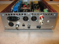
The optical input is in fact two inputs in one selectable from a switch on the back. There is the usual Toslink but also the real glass optical fiber ST, more on that later.
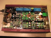
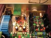
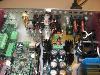
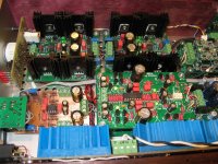
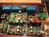
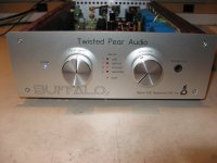
I also designed a nice compact enclosure. I had some parts from my previous Borbely headphone amplifier enclosure so it has to match it in size. But it pose a real challenge to fit all the Buffalo components inside. It ends up really well. Check the pictures
My setup is: MUX CS8416 (USB, Optical, Coaxial, AES/EBU inputs), Buffalo II (with Trident shunts), LCDPS Digital supplies for Buffalo & MUX with separate transfo, Dual mono Analog Placid shunt regulators (with separate transfo) for dual Counterpoint I/V converter stages, custom Legato (only the headphone section) amplifier, Volumite volume control, custom MUX source selector switch/Led PCB.
The optical input is in fact two inputs in one selectable from a switch on the back. There is the usual Toslink but also the real glass optical fiber ST, more on that later.
I also designed a nice compact enclosure. I had some parts from my previous Borbely headphone amplifier enclosure so it has to match it in size. But it pose a real challenge to fit all the Buffalo components inside. It ends up really well. Check the pictures
Attachments
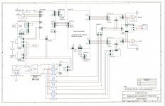
The complete DAC is rather complex with all these modules to integrate, connect and adjust to work together. The Buffalo II integration manual was of great help. I made my own complete interconnect diagram to document everything. It contains a lot of useful notes and reference readings. Here it is.
Attachments
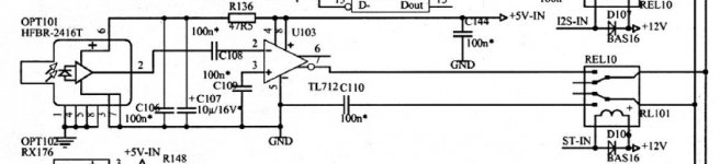
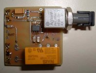
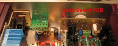
The DAC is using the MUX CS8416 input selector. To easily mount the different digital inputs on the back, and to receive the Toslink receiver circuitry, I did a small input PCB. At first I was planing to use an ST optical fiber input as well, but later decided to add it. It is mounted on top of this board. The ST pcb as the needed input switching relay and on board regulator and receiver. The switch between the Toslink and the ST is done there before going to the MUX.
I wanted a ST input because my ML37 transport has such great quality output. The real ST glass fiber is probably the best digital interface.
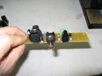
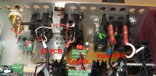
The last pictures is showing the input PCB with the back of the ST PCB on the rear of the DAC
I wanted a ST input because my ML37 transport has such great quality output. The real ST glass fiber is probably the best digital interface.
The last pictures is showing the input PCB with the back of the ST PCB on the rear of the DAC
Attachments
Last edited:
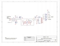
In order to control the MUX pcb you need to provide a digital code using two control lines 1 & 0. I wanted to have a compact circuit to do that, not just a switch because I needed to have indicators of the selected input, and to mount the Lock and Power leds. The little PCB I designed do just that and allows simple mounting on the front panel with just the rotary switch nut. It connects directly to the MUX input connector. I'm also using the MUX Lock pcb led to drive the front panel led. The MUX VD is supplying the needed 3.3V supply and it is used for the front power-on led as well. The pcb has provision to mount a local 3.3V in case the MUX VD supply was not enough for the job, but it works ok without it.
It is simple, and looks and works great.
It is simple, and looks and works great.
Attachments

Last edited:
Once I had all the parts, eventually everything worked great except I had a few problems. I was planning at first to use just one Placid for both Counterpoint IV (CP), but the Placid was not able to supply enough current while keeping enough current overhead to correctly regulate the voltage. Each CP needs about 120ma, and the headphone amp an other 30ma or so, for a total of 270ma. Add an other 50-60ma of CCS overhead, and the Placid was not able to operate at +/-15V output. Using two Placid witch one transformer each solved the issue.
Then I had a nagging noise issue with the output. At first I though it was caused by one of the Placid supply, but it was isolated to one of the Counterpoint that was oscillating like crazy and was producing at least 10mv of noise at the outputs (whatever the Volumite volume).
The Counterpoint is kind of old design for Twisted Pear and was supersede years ago by other I/V solution. It was a rather nice all discrete design, but no real documentation, except the schematic that was available.
It turns out the problem was caused by missing 4.7nF capacitors mounted directly at the input connector pins. There was a note on the schematic, but since there was already 4.7nF caps at the input and on the PCB I though they were the ones. But the note meant EXTRA caps...
Also there was the issue of connecting the AVCC point to the Buffalo or not. For better sound it has to be connected.
And finally the issue of the RG resistors to be connected on the GND pads.
A lot to cover and to discover going through the different Twisted Pear support forum. This is why I put together a quick Counterpoint User Manual, the first of its kind. It is not an official Twisted Pear manual, but was put together using Russ White comments and since he was the CP designer, it is better than no manual. It may be useful to some of you guys.
Attachments
Last edited:
While I was having noise problem, it was suggested to me that it could be caused by the MUX/Buffalo I2S flying wires or by the Volumite I2S flat ribbon cable I was using. Once I solved the CP parasitic oscillation problem, the Buffalo became completely silent. In my case the I2S cable doesn't seem to be an issue even if it is better practice to use shielded coax cable for the I2S and to route the Volumite cable away from the analog section.
I may do that later, but for now I measure a fraction of mv of noise at the output and the headphone output is perfectly silent even at full volume.
It is pretty good for me and now the Buffalo sound is superb. Thanks Twisted Pear.
I may do that later, but for now I measure a fraction of mv of noise at the output and the headphone output is perfectly silent even at full volume.
It is pretty good for me and now the Buffalo sound is superb. Thanks Twisted Pear.
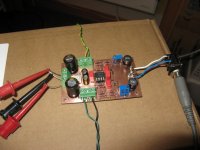
I was forgetting. I wanted to have an headphone amplifier buit-in. Twisted Pear has the Ventus EZ, but I needed two PCB that didn't fit into my enclosure. But they have the Legato, an I/V stage with a headphone amp section. I took out the Legato amplifier circuit and I made my own small custom Legato amplifier. I use one of the Counterpoint Placid shunt regulator to supply it. The high current LME49600 drivers are mounted under the pcb, in contact with the case bottom acting as an heatsink.
I couldn't believe this little amp sound, terrific.
I couldn't believe this little amp sound, terrific.
Attachments
Last edited:
Nice work!
I wanted to point out that the 4:1 S/PDIF Mux module now ships with the 4-Position switch board with LEDs included. I like your solution with the Lock LED as well.
I wanted to point out that the 4:1 S/PDIF Mux module now ships with the 4-Position switch board with LEDs included. I like your solution with the Lock LED as well.
- Status
- Not open for further replies.
- Home
- Source & Line
- Digital Source
- My Buffalo II DAC