Hello,
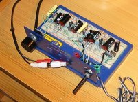
I'm sending a picture of my first homebuilt amplifier.
It was a totally spontanous project an rainy day.
I was looking at the diagram for my Quad33 preamp and tried, with my limited experience to figure out how to simplify by excluding tone controls and filters.
I already had one of the potentiometers, a "bread board" and an DC transformer from an scalextric miniracing track. I made an list and went to the local component dealer. Some hours later it was ready for test, and to my great surprise it worked and sounded not too bad!
Before I pick off the components, I want to figure out a way to reduce the gain in the Quad33 design.
On the original Quad33 there is a selector on the tape adaptor board for gain reduction, but I think there must be a better way than first reducing the signal just to amplify it again in the next step. My guess is that some of the resistors close to transistor tr401 shall be recalculated.
Does anybody know?
I'm doing this just for fun and to gain some better understanding.
My next bread bord pre-amp will be some design with OP-amps and if it seems promising I will build it in a permanent version.
Best regards
Robert
Attachments
Hi,
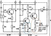
you can lower gain with disconnecting capacitor (50uF) in emiter of Q401 (blue on picture) or the better way, I think, replace resistors 1k8 and 470 in emiter of next transistor (red) with trimmer pot, let say 2k2. With this trimmer you can set negative feedback and overall gain, IMHO.
Your preamp looks good 😉
Regards
Attachments
Hi,
Thank you for your answer Moamps.
Since I opened this thread I have now borrowed a pair of computer speakers from my job. With theese connected I can test things with my experimental preamp without taking the risk to damage my own speakers or poweramp.
I tested to pull out the capacitor you suggiested, but the difference was very small, at least it was hard to detect in those cheap active speakers. The Idea was interesting. If I understood it right the plan was to keep the DC setup but reduce the AC signal.
I didn't test your suggiestion with the trimmer pot, but I'm quite confident it will work because I tested to increase the negative feedback by pulling out the 100ohm resistances on each side of the balance pot (not shown in the part of the diagram you posted) and that reduced the gain.
I don't know the optimal amount of negative feedback in the design and I don't understand how to determine it and why.
Peter Walker must however has got an opinion about it once when he made the design.
I also implemented an other change in the design.
I have reconnected the two 2.2uF capacitors in the middle of the diagram so there is one for the signal and on for the negative feedback. The amount of capacitors in the signal path is reduced by one in this way. This become possible becausse I don't have the bass and treble controls.
Robert🙂
- Status
- Not open for further replies.