Hi all!
I need to make a mute switch for a Mipro wireless bodypack. Using the on/off switch it takes as much as 3 seconds for audio to start.
Prefferrably I would like only two wires for this external switch; grounding something that quietly(no pops or clicks!) mutes audio.
I have no schematics for the Mipro transmitter (yet), but maybe someone could come up with some idea that I could try?
Since the mic capsule needs phantom power, all efforts trying to short or break the wires to the mic results in loud pops and clicks...
Best regards to all genious minds out there!
Jan Sjoberg
Sweden
You have to place a capacitor around 10uf @ 6.3V in series with a resistor around 10,000 ohms across the audio to ground circuit. That way the capacitor charges up and you don't hear a pop when you short the resistor to kill the audio.
Further explanation?
Thanks for your answer!
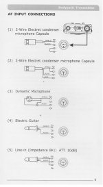
The only schematic I've got is attached. It is number (2) in the image.
Could you please explain how I should connect things?
Doesn't the capacitor and resistor affect frequency response?
How about polarity for the capacitor, or is it bipolar? Electrolytic or foil? Does it matter? Size is of some importance here...
Best Regards,
Jan
You have to place a capacitor around 10uf @ 6.3V in series with a resistor around 10,000 ohms across the audio to ground circuit. That way the capacitor charges up and you don't hear a pop when you short the resistor to kill the audio.
Thanks for your answer!
The only schematic I've got is attached. It is number (2) in the image.
Could you please explain how I should connect things?
Doesn't the capacitor and resistor affect frequency response?
How about polarity for the capacitor, or is it bipolar? Electrolytic or foil? Does it matter? Size is of some importance here...
Best Regards,
Jan
Attachments
- Status
- Not open for further replies.