I have just had the pleasure of repairing a friends 18 year old MF A1-X class A amp that has been out of commision for a few years. The 0.47 Ohm PSU filter resistors were burnt out. I replaced them and viola - working again.
I looked at Mark Hennesy's excellent page about this amplifer for the circuits, and must admit I winced - that volume control, the double feedback network, 'lytics everywhere. Well, those are my engineering prejudices. Reality is a bit different.
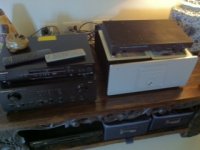
Hooked up to my B&W 702's this little amp blows the Marantz PM7000 away - very smooth sweet sound and I am most impressed. Of course its no match for my Ovation amp but that is a 250W monster. I could happily live with this for a second amp for jazz and light chamber music. Heatsink temperature after about 40 minutes was 55C BTW (measured with a gun type IR thermometer)
I real little classic - awsome!
I looked at Mark Hennesy's excellent page about this amplifer for the circuits, and must admit I winced - that volume control, the double feedback network, 'lytics everywhere. Well, those are my engineering prejudices. Reality is a bit different.
Hooked up to my B&W 702's this little amp blows the Marantz PM7000 away - very smooth sweet sound and I am most impressed. Of course its no match for my Ovation amp but that is a 250W monster. I could happily live with this for a second amp for jazz and light chamber music. Heatsink temperature after about 40 minutes was 55C BTW (measured with a gun type IR thermometer)
I real little classic - awsome!
Attachments
I've not seen inside these before, thanks for the pics, Bonsai.
What are the thick, square sections - heatsink extrusions?. Even at 2 x 10W, it must run hot throughout but that's nothing new for MF.
Are you contemplating a 250W version for a shoot-out? 😀
What are the thick, square sections - heatsink extrusions?. Even at 2 x 10W, it must run hot throughout but that's nothing new for MF.
Are you contemplating a 250W version for a shoot-out? 😀
Hi Ian,
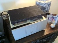
Yes, that's the A1 sitting on top of the 250W Ovation. That's got 5 pairs of 21193/21194 biased up at around 120mA per pair, so it's got a few watts of class A!
The A1 has an inverted U section inside and the output devices are mounted on this. The inverted U section is then coupled to the top plate with some Heatsinks compound and 3 screws.
Surprisingly good sound for such a little amp, and especially the idiosyncratic line stage.
I returned the amp to the owner today an he was pretty pleased.
would it help understanding if we that know referred to maximum ClassA output current rather than referring to maximum ClassA power?That's got 5 pairs of 21193/21194 biased up at around 120mA per pair, so it's got a few watts of class A
5pr @ 120mA bias gives a push pull output stage a maximum ClassA output of just under 1.2Apk.
I would finish the sentence from above with "so it's got 2.3Apk of ClassA".
That seems unambiguous and informative.
Well...Audio Amplifier Design and Circuits | hifisonix.com has a bit more info for others if Bonsai doesn't object.
'Wonder how it sounds (or not) since the big bang and dash for SSRs?
'Wonder how it sounds (or not) since the big
bang and dash for SSRs?OOPs
I doubled the ClassA current twice.
I can't do that.
It should have said
"so it's got 1.1Apk of ClassA".
I doubled the ClassA current twice.
I can't do that.
It should have said
"so it's got 1.1Apk of ClassA".
It's fixed and singing again Ian.
The cause of my mishap: two 2 pin mains sockets next to each other. One wired for 110 the other for 220. That's why it fried up.
I found out because I have a 1kva transformer that I wired up to take in 100vac in Japan and give me 220vac out. Well, I tired the same trick here and the transformer buzzed and the mains tripped. I checked my wiring, it was ok, checked the voltage on the input and it was 218vac.
Luckily, after I repaired my amp, I had plugged it into the LHS socket.
The CD player is universal mains input, and this was plugged into the 220vac socket, so I never suspected.
BTW there are four 220 sockets in the house. I would have thought they would have at least used a different type of socket.
....and must admit I winced - that volume control, the double feedback network, 'lytics everywhere. Well, those are my engineering prejudices. Reality is a bit different.
🙂 Just curious, what is it about that volume control ?
So the question from my viewpoint is:
Does stating the ClassA current provide more information than stating the ClassA power?
Which way would do better service to the DIYaudio community?
Does stating the ClassA current provide more information than stating the ClassA power?
Which way would do better service to the DIYaudio community?
Scratchy by design. Some people have replaced the whole preamp for its multiple issues and generally been a lot happier since.🙂 Just curious, what is it about that volume control ?
The volume control is implemented with a pot in the feedback loop of an inverting stage opamp, so volume control is achieved by altering the stage gain. It's a TL084 so the bias currents are low, but of course you are hanging a pot and wires off a summing junction. Not ideal for noise pick up. I can think of a reason or two why this was done, but this is suboptimal compared to a conventional pot arrangement. The designer was Tim Depavarachini (spelling?) who normally does tube stuff, but why he did this, only he knows.
:-/
:-/
I think the gain variation for volume control was done by another renowned SS designer. Was it Stan Curtis?
Not sure Andrew, but it is not a good approach in my view. It's clearly done in the interests of minimizing the perceived line stage noise. I would think running the line stage gain at 14db or so with +- 15v rails and placing the volume potentiometer after the line stage would be a better solution. You still get >20dB overload margin ref 1V out
Mark Hennesy's solution is simple and elegant also using a 5532
Mark Hennesy's solution is simple and elegant also using a 5532
Last edited:
but this is suboptimal compared to a conventional pot arrangement. The designer was Tim Depavarachini (spelling?) who normally does tube stuff, but why he did this, only he knows.
Surprisingly good sound for such a little amp, and especially the idiosyncratic line stage.
Therein lies the answer. 😉
I think the gain variation for volume control was done by another renowned SS designer. Was it Stan Curtis?
No, it was Tim de Paravincini. We corresponded about the design a few years back...
I am looking for A1/A1-X/A100 in faulty condition
For the development of an outdoor power supply solution and a conversion for smaller max. output power and increasing the quiescent current at the same time, I am looking for a defective device of the A1 or one of the similar models (A100, A1-X, David, etc.). which also use a heat sink as top cover.
Who has such a device (e.g. with def. mains transformer), which for the owner a repair effort would be too expensive (e. g. in case of a faulty mains transformer)?
Thank you for offers.
a detailed circuit description can be found in english here
Musical Fidelity A1 › Technical
and in German here:
Freie Ton- und Bildwerkstatt: Musical Fidelity A100-X
Freie Ton- und Bildwerkstatt: Musical Fidelity A100-X
Freie Ton- und Bildwerkstatt: Musical Fidelity A1
- Home
- Amplifiers
- Solid State
- Musical fidelity A1-X