Hi guys,
i am trying to fix my amp. Both channels are working, but the amp is extremly hot after few minutes.
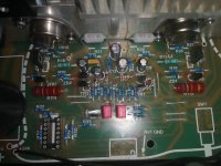
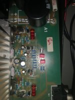
Resistors R1 and R2 (0,47ohm, 2W) are burned. I changed them for 5W so that i can make some measurements.
Power supply voltage should be around 24V, but when I turn it on its about 22V and its going down to 19V.
I had 1V Dc on output of left channel.
I checked all transistors, elcos and resistors and everything looks fine.
I disconnected Emitter and Base from TR9 and TR10. Now power supply voltage is around 24V and resistors arent hot.
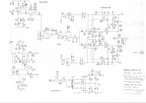
With R6 and R11 3,9Mohm and R30 and R31 0,22ohm i should get sth about 700mA BIAS current.
Why I am getting much more?
i am trying to fix my amp. Both channels are working, but the amp is extremly hot after few minutes.
Resistors R1 and R2 (0,47ohm, 2W) are burned. I changed them for 5W so that i can make some measurements.
Power supply voltage should be around 24V, but when I turn it on its about 22V and its going down to 19V.
I had 1V Dc on output of left channel.
I checked all transistors, elcos and resistors and everything looks fine.
I disconnected Emitter and Base from TR9 and TR10. Now power supply voltage is around 24V and resistors arent hot.
With R6 and R11 3,9Mohm and R30 and R31 0,22ohm i should get sth about 700mA BIAS current.
Why I am getting much more?
Attachments

Yes, i have one old Philips PM 3200 😀Could be it's oscillating at some ultrasonic frequency.
Do you have a scope?
Should I go with the probe on TR6, TR8 Emitter?
On resistor R16 i am getting 4V, but on the R15 should be about 2,6V ( I am getting 4V)
I did some measurements and I found some strange oscillations on resistor R26.
Sinus wave in 2 div, Scope set on 0,1us so its like 5Mhz?
R28 on the other side of the circuit was just fine.
Can sb give some tips what can I do now?
Sinus wave in 2 div, Scope set on 0,1us so its like 5Mhz?
R28 on the other side of the circuit was just fine.
Can sb give some tips what can I do now?
Schematics which I posted few day ago are from Mark Henessy page.
I dont understand why TR6 is oscillating.
Basis -21,3V
Collector -4,2V (should be about 2,6V, but I am getting around 4V in both channels)
Emitter -21,9V (looks like some Sinus signals)
Does it mean BD139 is faulty?
I dont understand why TR6 is oscillating.
Basis -21,3V
Collector -4,2V (should be about 2,6V, but I am getting around 4V in both channels)
Emitter -21,9V (looks like some Sinus signals)
Does it mean BD139 is faulty?
Decoupling is done with R15 330 and R19 2k2 right?Lack of decoupling on the rail?
They are fine.
You could try adding high frequency bypass (decoupling) caps across the power supply filter caps C2 and C4 from the rail to ground. Something like a 0.1 uF ceramic cap, and placed close to the emitters of the output transistors. The value is not really critcal, it just needs to be a low impedance path at high frequencies.
I presume this amp worked properly before and this is a new problem, so it could be the filter caps have aged and increased their ESR at high frequencies.
This may not fix it, but at least it should eliminate one possibility, and be fairly easy to try.
I presume this amp worked properly before and this is a new problem, so it could be the filter caps have aged and increased their ESR at high frequencies.
This may not fix it, but at least it should eliminate one possibility, and be fairly easy to try.
I already had a few devices of this model for service, but have never observed these unwanted RF oscillations here.
But I have to say that I never did the actual troubleshooting as a first step; troubleshooting always I have performed after replacing all parts, which, as we all know, is routinely replaced before doing further steps due to age.
Are C11/C12 (680pF) in right condition ?
Or BD135/136 was replaced by a newly purchased type of unknown origin ?
If not and all usual replacements are already performed, I would swap the parts in question between the left and right channels until this RF effect can be observed on the other channel.
It could be helpful to increase the 0R22 resistors so that the quiescent current through the output stage is only 30-50mA in order to examine the DC conditions in all stages and examine for RF oscillations without thermal stress for the output devices.
But I haven't done this myself yet - there may be a better method for reducing the quiescent current in the output stage for long time trouble shooting.
check out also the results of my question in post #12 under
https://www.diyaudio.com/community/threads/musical-fidelity-a1-re-build.340990/#post-7638640
Cautionary advice: be sure to use x10 probes when probing with scope. The high capacitance of x1 probes can provoke oscillation, especially at internal nodes within an amp.
I'm not intending to argue that oscillation isn't a major suspect.
Good luck!
I'm not intending to argue that oscillation isn't a major suspect.
Good luck!
I changed my Probe to x10 and there is still oscillation.The high capacitance of x1 probes can provoke oscillation
With TR9 and TR10 sth about 22V sinus 2MHz
I also noticed that capacitor C32 was missing so I placed 220nF there.
Reichelt.deOr BD135/136 was replaced by a newly purchased type of unknown origin
I replaced old caps with Jamicons 10mF/35V 105°Cit could be the filter caps have aged and increased their ESR at high frequencies
The problem is still there. I connected TR9 and TR10 again and there is still no difference.
Output Voltage measuered on Speaker terminals swings 0-300mV and the Power Supply Voltage lowers to 18-19V.
Last edited:
R17 and C12 form a lag-lead network and if that path has failed, oscillation might result. Make sure both are functional, that C10's ESR is low re R17. Confirm PCB trace integrity by confirming lead-to-lead continuity from R10 to TR4 base, R10 to C10, C10 to TR4 base. There are just shots in the dark.
You noted oscillation at R26. Is C12 ok? What's the repair history on TR5, TR6, TR9?
I would focus on curing oscillation first, then check and modify bias current if necessary. Look at voltage across R22 and R23; any DC drop is an indication of leakage through their respective caps and will contribute to increased bias current. Increasing R6 and R11 will lower bias current. I believe adjusting their relative ratio will affect amp output offset voltage.
Reichelt is a supplier not a manufacturer. AccordingReichelt.de
https://www.reichelt.de/de/de/bipol...G3JiOhQMVJqiDBx1rDQ9TEAQYASABEgLjC_D_BwE&&r=1
the manufacturer is CDIL from India - go to
https://www.cdil.com
and I haven't experiences with the quality standard.
Maybe ST - go to
https://www.mouser.de/ProductDetail/STMicroelectronics/BD135?qs=DcAdhm6iCnquzRqyLiHtjA==
or Onsemi
https://www.mouser.de/ProductDetail/onsemi/BD135?qs=vNc2DXHODiKggscsWFsSpw==
is to prefer.
- Home
- Amplifiers
- Solid State
- Musical Fidelity A1 Left Output Problem