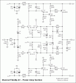
Stormrider said:Anybody ever cloned an A1? The circuit is simple with cheap/available parts. Supposedly it puts out about 8w in class and then up to 35w in AB making it an A+AB correct? Any PCB designs around?
You could always design your own PCB ?
There are plenty of free packages around.
Or try ebay.
I think there are some much better circuits around than this.
Do a search on the forum and you will find a lot of good amplifiers you can build - class A and AB
Do a search on the forum and you will find a lot of good amplifiers you can build - class A and AB
Yes you can find the PCB at the ebay store "tubehunter" from china the kit is 31Usd + shipping.
If someone buy this kit please copy the pcb layout an post it!
If someone buy this kit please copy the pcb layout an post it!
Yes, i saw the kit on ebay and thats what prompted my post. I did find another thread here on diyaudio and someone there made there own PCB but it seems to be based on a different version of the A1.
Whats wrong with this design Bonsai?
Whats wrong with this design Bonsai?
Does anybody have a schematic for the A3CR? I would be curious to know what the topology looks like. I had a chance to have a look under the hood of a friends amp, but I was a bit short of time and it would have been quite some work to get access to the track side of the PCB, so I never had a chance to reverse engineer it.
jjanderson said:Where did you find the PCB on the forum?
Is there a link to download?
http://www.diyaudio.com/forums/showthread.php?s=&threadid=73692&highlight="musical+fidelity+A1"
I have a few questions about the function of this circuit. There is no bias control, so how would you set the quiescent current to 700-800ma like the bottom of the diagram suggests? Also, the dc offset output would relay on how well the input transistors pairs and drivers are matched, correct?
It will probably be awhile before i build this but i want to get some of the planning out of the way so i can collect the parts needed over time.
I'm going to use an 18-0-18 transformer so the DC rails will be +/-24vdc or so. 300va to 400va depending on whats cheap on ebay at the time. 🙂
I'm planning on using better transistors than those specified in the circuit since i already have them. BD136/135 will be replaced with MJE340/350 and BC184/214 with BC546/556. Anyone see any problems with these changes?
MJ15001/02 outputs are basically the same price as the 2N3055/MJ2955 pairs at digikey, so I'll probably go with those as outputs, or should i just step it up to MJ15003/04 pairs?
- Status
- Not open for further replies.
- Home
- Amplifiers
- Solid State
- Music Fidelity A1
