I have a Music Angel XD SE integrated amplifier, it has a few glaring issues I need to fix before using. For what I paid for it I wasn't expecting perfection, and I didn't get it. Stainless steel chassis, 4 EL 34, nice transformer covers, etc. However,
1 - The IEC socket has NO electrical connection to chassis ground. I don't want to plug it in until thus is fixed. The inputs (RCA's) and outputs (4 or 8 ohm connections) all float with no connection to chassis ground EXCEPT a wire under the input section PC board has a ground wire connected to where the input ground connects to the PC board(?).
I don't have any paperwork, like owners manual or schematic and every wire from the power supply pc board are black. Actually, every wire is black although some have a cloth wrap over them, mainly the wires to a from the four transformers.
What is a safe way to connect chassis ground to the IEC? Can I just connect a wire from the chassis to the IEC ground terminal?
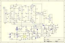
Does anyone have a schematic for this amplifier? Ones I have found on the web don't seem to match the wiring of this amp.
1 - The IEC socket has NO electrical connection to chassis ground. I don't want to plug it in until thus is fixed. The inputs (RCA's) and outputs (4 or 8 ohm connections) all float with no connection to chassis ground EXCEPT a wire under the input section PC board has a ground wire connected to where the input ground connects to the PC board(?).
I don't have any paperwork, like owners manual or schematic and every wire from the power supply pc board are black. Actually, every wire is black although some have a cloth wrap over them, mainly the wires to a from the four transformers.
What is a safe way to connect chassis ground to the IEC? Can I just connect a wire from the chassis to the IEC ground terminal?
Does anyone have a schematic for this amplifier? Ones I have found on the web don't seem to match the wiring of this amp.
welcome to the marvelous world of music angel !!
by the way,quasi all of your amp have a different diagram , pcb and wiring .
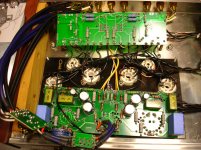
can you take a few pics inside of your amp to see all pcb ? and other one pics
to see exactly the model because "xd se " is general name off quasi all music angel amp 😉
by the way,quasi all of your amp have a different diagram , pcb and wiring .
can you take a few pics inside of your amp to see all pcb ? and other one pics
to see exactly the model because "xd se " is general name off quasi all music angel amp 😉
Yes, a safe way is to connect a wire directly from the IEC socket ground terminal to a near by chassis ground point (nut/bolt). This wire should be sufficient to handle any possible electrical and mechanical stress applied to it. The function of this wire is to dump any accidental high voltage current to the house ground (their by trigger any safety device hooked up to it (ie. fuse & leakage detection).
Just check the black (0 ohm) speaker post with a DVM to chassis ground. If you don’t have continuity, ground each as you do the IEC.
beware with music angel amp ,some have the ground of the input pcb directly on the zero of the secondary opt,that's why I asked for pics inside of the amp.
Last edited:
I found the wiring diagram online, my version is the XD500t. The input grounds are attached to chassis ground, this I removed. The 0 speaker lead is NOT grounded to the chassis, only the input wires ground (?). I wired the IEC ground to chassis ground, removed the input wires ground, and I'm waiting for two CL-60's to wire the pc boards ground to chassis ground to isolate the pc board ground, yet still have the safety of a chassis ground.
The schematic has different part values than the actual amp has, like the cathode resistors for the EL34's are 22 ohms, not the indicated 12 ohms.
I'm going to install 1 ohm 1 watt resistors in series with each EL34 cathode for a bias test point, and then use a 50 ohm 25 turn pot instead of the 22 ohm cathode resistor to adjust bias for each tube.
Captn Dave - Should I just wire the 0 ohm speaker posts to ground or should I use the CL-60's to isolate the output transformers?
Attachments
Here are some pics inside the amp, I have since replaced the volume control the a precision resistor 24 step, and the input selector for 4 inputs, my amp only had two sets of RCA's. I drilled the chassis for the two additional RCA's, what a job! Stainless steel is as hard as a rock, once I was able to penetrate the chassis, drilling was easy. I changed the cutting angle on the drill bit to a 4 degree sharper angle to cut the stainless. My Drill Doctor is so handy for things like this.
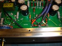
Notice the plate resistor burned from a set of EL34's that had an internal short. I replaced the resistors with 5 watt versions.
Notice the plate resistor burned from a set of EL34's that had an internal short. I replaced the resistors with 5 watt versions.
Attachments
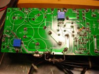
you can also check/change all power supply capacitors (specially for the voltage doubler)
also increase the capacitance of the time constant capacitor of the timer 555 (22uF25v to 100uF25v) which will give you +/- 1 minutes of start delay.
as you can see, there is nothing in the two small boxes between the power supply and the opt, that's why you have one (two) filter resitances after b +.
if it has burned, you must have a sick capacitor and / or an excessive bias.
I also advise you as long as it is necessary to check the diagram and to note it clearly to know what you have because I repeat it, they are all different.
for example, on one of my xdse 800 there was a 2.8k grid resitance per tube ... and 2.2k cathode resistance ...
Attachments
I like the schematics, very easy to read. I understand how the diagrams component value will differ, just makes you wonder, why so many variations? Good point regarding the caps, was it the power supply that did in the tubes, or the tubes doing in the power supply resistors? Right now is a good time to replace the caps. Thanks to everyone for the help.
- Status
- Not open for further replies.
- Home
- Amplifiers
- Tubes / Valves
- Music Angel XD SE amplifier