Hi, I was wondering if anyone could have a look at this circuit and let me know if its ok? I am going to hard wire the amp and get rid of the flimsey circuit board that holds the input tubes. I have allready removed the feedback and a few resistors as per an article on another site but most of the mods had allready been done by the manufacturer. I dont have a real understanding of tubes so I just want to make sure there are no design faults that could show up later, allthough I have been running it for over a year with no probs. I have copied the circuit direct from the pcb, there seems to be a lot of inconsistancies with the original schematic as far as component values are concerned, even the values printed on the pcb dont match. I have not changed any resistors, I stripped one half and measured every one. I would like to know if R15 is needed as its not on the schematic? Any ideas, tips to improve the circuit would be greatly appreciated, I seem to remember reading that electrolytics in a valve amp should have a resistor across them, is this specific or good practice for all lytic caps? I am more than happy with the results from the mods ive done, including changing all the 100nf caps with audio grade versions of 2.2uf, I just want to make sure ive drawn it correctly and the designer hasnt made any bad choices for resistor values. Incidently ive allready hard wired the amp for triode mode, my main aim is to change the lytics (there is just no height avail to do this with the pcb installed) and to upgrade the resistors for naked bulk foils where advantagous, this is also where I need help as there seems to be certain places where CC's are recomended? I havnt rulled out grid chokes either.
Many thanks
Many thanks
Attachments
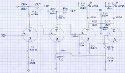
Why are R8 and R16 not identical? They should be. You also have a small (probably useless) grid stopper resistor on one side of the driver and not the other- I'd probably use one on both sides (grid stopper should be wired as physically close to the grid pin as possible) and increase the value to 1k.
Why are R8 and R16 not identical? They should be. You also have a small (probably useless) grid stopper resistor on one side of the driver and not the other- I'd probably use one on both sides (grid stopper should be wired as physically close to the grid pin as possible) and increase the value to 1k.
Hi SY, many thanks for the reply, I think R8 and R16 are not identicle because they are poor quality components, I have drawn the circuit as it is rather than as it should be, theres no point posting the original schematic because it doesnt relate to the pcb. As mr Fikus noted, no 2 amps are the same!
As for the grid stopper, do you mean R9? I am sorry I am a complete amature and rely on people that know what they are doing! If you do mean R9 then its not small, its 2k so I am guessing they have saved a penny/space and used one 2k instead of two 1k's? the resistor is connected directly to pin 3 on the pcb and there is a link between 3 and 8, thats why I drew it like that. Now you have pointed that out I will use 2 1Ks though when I hard wire it, Thanks.
Alan
The grid stopper is R15 (shown as 22R).
Oh that little bugger! yeah thats one of the reasons for me posting and 1 inconsistancy I was talking about. There is no 22R/grid stopper on the original schematic and R16/R8 are 100k. Is it necessary?
Alan
- Status
- Not open for further replies.