I'm building a Millenium 5-20 Valve amplifier but only have a 115V output transformer.
The transformer is rated at 220VA so should be good for 115V at about 2A.
My amplifier requires 450VDC at 250mA.
I'm using 1N4007 and 220uF caps in the multiplier.
Why is the voltage regulation so poor ?
Testing the multiplier with a 70W load I get the desired 415VDC but it is still over 500VDC off load.
Dear Katie,
Please tell your dad that as far as I recall you loose a lot of charge by swapping the charge from one capacitor to another. This means that your output power is much less than your input power. Further, that your output impedance becomes high and you have the type of drop you observe.
You can use a shunt-regulator to perform active regulation.
Could you eventually post a simple sketch of the voltage multiplier you use?
Larger caps in the multiplier would help with regulation. You are using a multiplier, in this case probably a tripler and all of the capacitors are essentially in series.
Also the unloaded voltage on the transformer will also be tripled.
Also the unloaded voltage on the transformer will also be tripled.
Last edited:
...it is still over 500VDC off load.
So, a tripler, not a doubler??
You better draw it out. There are several ways to do it, and it matters.
short summary - all transformers have regulation as an issue, te difference between 0 and full-load volatge output. Geneally rathe worse with E-I types tan toroidal of teh same VA cacpity.
However - even if the multiplier, or tripler, was somehow 'perfect' - in terms of output regulation, you will see 2x (or 3x) the on-load sag of the basic transformer. IT is a multiplier.
So if you expect, say, 15v drop at the transformer under your prospective load current; and you use a voltage tripler that is 'perfect', well - yes, 50v sag on the tripler output under the same prospective load is about exactly what you should expect.
TBH all the caps involved are going to have a hard life, and the raw V supply to your rectifier will always be all over the place (how stable is your local AC Mains...? that adds to the problem , too...)
Unless you only need a mA or ten - buying the transformer you really need is, I think, the better answer every time. Sorry.
Thank you all for your replies.
I've gone for the correct transformer.
My only issue now is that while the valves are not conducting, the B+ is excessive.
I've gone for the correct transformer.
My only issue now is that while the valves are not conducting, the B+ is excessive.
Thank you all for your replies.
I've gone for the correct transformer.
My only issue now is that while the valves are not conducting, the B+ is excessive.
This is why guitar instrument tube amps have 'standby' switches. So the tubes are heated and ready to go when the high voltage rail comes up, making sure the marginally rated electrolytics do not see too high voltage too many times. (The standby switch turns on the high voltage, while the on/off switch turns on the heaters. So turn on the amp, wait a bit - count slow to ten, flip the standby...voila).
Modern tube amps that do not technically need the standby switch for that reason still often include the standby because the guitarists use them as mute switches as well.
Better is the suggested shunt reg by Mr.FauxFrench, which draws a bit more current when the tubes are not, and will draw less as the tubes start to draw current. This gives a relatively constant load on the voltage rail.
Last edited:
I can't see how a shunt regulator could be implemented as it would have to dissipate over 100W.
Maybe a 30 second ON timer for B+.
Maybe a 30 second ON timer for B+.
Not so difficult I believe. You define the maximum voltage you can tolerate. You put the shunt activation threshold at that level. For the short moments where the valves are not active, the shunt holds the voltage at the limit. When the valves are active, the shunt draws no current.
Unless the shut can handle over 100W continuously. Admitted, I have no experience with vacuum tubes but there must be some kind of predictable outcome when you turn them ON. If not, include a thermo-fuse.
I think you need a bleeder.
In case of filtering with an inductor ahead, as frequently done with tube technology, you need some load to avoid this issue. A bleeder resistor.
In case of filtering with an inductor ahead, as frequently done with tube technology, you need some load to avoid this issue. A bleeder resistor.
Are your components so rated that they will not stand the 15% overload during start-up?
Electrolytic capacitors have a specified surge voltage higher than the rated maximum voltage which can be found on the data sheet.
https://www.tdk-electronics.tdk.com...2da2adf2b/pdf-generaltechnicalinformation.pdf
'3.1.3 Surge voltage VS
The surge voltage is the maximum voltage which may be applied to the capacitor for short periods of time, i.e. up to 5 times for 1 minute each per hour.'
Ensure your components can withstand the off-load voltage and enjoy.
I insist that smoothing with LC versus RC makes a lot of difference about voltage and behavior with load or no load.
Now, a schematic or full description would help.
Now, a schematic or full description would help.
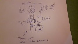
Here are bleeder suggestions I have used. Lamps dissipate heat well, act as indicators, and are simpler than trying to make a power resistor handle > 10W.
PMOS is a FQP3P50 but I have never used it above 400V. You can either cascode it, get one with higher voltage rating, or bet the rails never go above 500V (which is what I would do).
PMOS is a FQP3P50 but I have never used it above 400V. You can either cascode it, get one with higher voltage rating, or bet the rails never go above 500V (which is what I would do).
Attachments

A timer is a good idea.I can't see how a shunt regulator could be implemented as it would have to dissipate over 100W.
Maybe a 30 second ON timer for B+.
However, I would firstly try, just adding a bleeder resistor.
With a resistor value to waste power in this resistor about 20% of the power in the load.
This should improve load regulation, and hopefully be good enough.
- Home
- Amplifiers
- Power Supplies
- Multiplier Regulation