I just finished an ACA, and I'm about to finish a J2 clone. I've read all the Broskie articles on SRPP, IMC, and SRPP+, but I still don't know how one modifies an NP design when it comes the the Mu Follower portion of the amp.
When NP explains the way his circuit works, there's always a part where I lose the line of reasoning on why a part of a certain value was chosen, or how that part works in the Mu Follower.
Can I ask those who understand such things to walk me (or us if others are also lost) through an Mu Follower of NP's design? Perhaps the ACA? To be explicit, how is the ratio of resistors determined in the Mu Follower? Size of the Cap? Voltage of the circuit? How can one modify these things for better outcomes when one modifies a circuit?
answer one :
answer two:
with so many question , you're really asking for complete walk-through of one's career ; read ACA threads and article again ; think small , then bigger from that .
answer three : every construction is Lego-like dance with compromises
answer 4 : I'm studying Papa's practical jokes for years now ; and now I only know more about my lack of knowing
An externally hosted image should be here but it was not working when we last tested it.
answer two:
with so many question , you're really asking for complete walk-through of one's career ; read ACA threads and article again ; think small , then bigger from that .
answer three : every construction is Lego-like dance with compromises
answer 4 : I'm studying Papa's practical jokes for years now ; and now I only know more about my lack of knowing
answer one :
answer two:
with so many question , you're really asking for complete walk-through of one's career ; read ACA threads and article again ; think small , then bigger from that .
answer three : every construction is Lego-like dance with compromises
answer 4 : I'm studying Papa's practical jokes for years now ; and now I only know more about my lack of knowing
ZM - You often try to redirect threads. I thought the Pass section of the forums was the exact place to ask a walk through of the Mu Follower NP uses. I've read every article NP has written, as well as many on TubeCad, but without an electronics background, I need more "hand-holding" to understand what's happening.
It's easy for someone with a EE to say "read the article". I have an MD, I would never tell a patient with a question "read the article". Perhaps,with your expertise, you can walk us through the Mu Follower. I can tell you most of the people I know on this forum have no idea how it works.
You right, from my experience, doctors don't say " read that", coz most of them think that mortal ppl that" because they think that we mortals just don't capable of digesting any part of the knowledge they have ;-).
I think ZM had demonstrated here that he always help and answer the questions when they are a bit more specific ;-).
I know it was just the way to start the topic, but you asked more like: " I do not know much about my-followers, but I want to improve Pa's designs" 🙂.
Imagine if patient comes to you and says: " I have seen another doctor's opinion on something, it is kinda cool, but I want to (read lets say an MRI) make one better" 🙂.
You would probably say that radiologists study for n-years to do that 🙂.
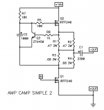
In the RO85 thread, you have one of the most complete descriptions you will find. To understand further, just modify the ACA by adding a two 10R pots across R1-R4. One output of the pot should feed the bottom of C2 and the other should feed the output of the amp. You will be able to vary the operating condistions of the amp in a couple different ways. I believe this quote will help explain it better than I. You will n eed to be able to measure distortion to truly apprreciate the exercise. I may have this wrong, so perhaps someone will chip in and correct my errors, if present.
http://www.diyaudio.com/forums/pass-labs/190438-ss-120r085-depletion-mode-jfet-11.html#post2613234
http://www.diyaudio.com/forums/pass-labs/190438-ss-120r085-depletion-mode-jfet-11.html#post2613234
Attachments
Last edited:
And even after I read all the threads and articles, in the end it is all about the sound (THD spectra) you like for the current parts and topology 🙂. I know, many it is because I do not have a THD analyzer 🙂
ZM - You often try to redirect threads. I thought the Pass section of the forums was the exact place to ask a walk through of the Mu Follower NP uses. I've read every article NP has written, as well as many on TubeCad, but without an electronics background, I need more "hand-holding" to understand what's happening.
It's easy for someone with a EE to say "read the article". I have an MD, I would never tell a patient with a question "read the article". Perhaps,with your expertise, you can walk us through the Mu Follower. I can tell you most of the people I know on this forum have no idea how it works.
answer one - I don't have one day of formal education in field of electronic
answer two - you can see me trying to redirect threads when I have impression that ppl are poking things which Papa evidently didn't share and don't wanna share ...... which certainly isn't case here
answer three - look for Wensan's threads ; but - if you really already read everything you mention , how on earth someone with limited patience for use of non-native language ( as is case with moi ) can write you a book ?
answer four - however , if blaming me makes you feel better , just go for it ...

answer five - buy me that drek from the pic , and I'll write you a book ; buy it for your self , and World is your Oyster (maybe)
edit:
answer six - you really got complete information/answer with that AP pic ;
Last edited:
In the RO85 thread, you have one of the most complete descriptions you will find. To understand further, just modify the ACA by adding a two 10R pots across R1-R4. One output of the pot should feed the bottom of C2 and the other should feed the output of the amp. You will be able to vary the operating condistions of the amp in a couple different ways. I believe this quote will help explain it better than I. You will n eed to be able to measure distortion to truly apprreciate the exercise. I may have this wrong, so perhaps someone will chip in and correct my errors, if present.
http://www.diyaudio.com/forums/pass-labs/190438-ss-120r085-depletion-mode-jfet-11.html#post2613234
NB that , for that test of ACA upper part , one need to differentiate DC path ( bias of mosfet ) and AC path (modulation of mosfet gate )
so - emiter of bjt needs to stay where is it , while bottom of cap can be driven via viper of pot , proposed bu you
I forgot to say - sorry , still digesting first morning coffee - to be able to do that , one need to introduce few more resistors , to make both paths (dc and ac) equal in wiev of mosfet's gate 😉
lazy to sketch that now , but let's say - equal (several K) resistors from gate to cap and from gate to bjt's collector
.... or cap directly to gate , with ,say,4K7 to 10K to bjt colector
lazy to sketch that now , but let's say - equal (several K) resistors from gate to cap and from gate to bjt's collector
.... or cap directly to gate , with ,say,4K7 to 10K to bjt colector
Last edited:
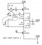
Oh, the Zen Pot, here is it again, allows a fine tuning of k2 to k3 ratio!
It is a pleasure to see it at the PC, how the values change....😀😀
It is a pleasure to see it at the PC, how the values change....😀😀
yup
common Papa's practical jokes .........
he's almost banging us in da head with tricks , all these years
common Papa's practical jokes .........
he's almost banging us in da head with tricks , all these years
- Status
- Not open for further replies.
- Home
- Amplifiers
- Pass Labs
- Mu Follower design in NP's Amps