Ok so i got 2 of these 2301 amps i bough broken. After some parts around, i got 1 working. The second one had blown ps fets, gate resistors, ps drive transistor resistors, a shorted diode that i think the factory installed inplace of a rail cap and the inductor seemed to have some heat damage and a prior attemp to repair.
I got the amp to idle, even tho it was running hot and producing sound. Well here is were my problem starts.
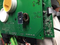
The output inductor had previously been messed with. It showed signs of overheating. Before powering the amp i took it out and compared it to the working amp. First thing i noticed is that it was installed incorrectly as if it got turned 90 degrees. I checked it for shorts between the two windings and it checked ok. Due to the burned wires, i had to cut some wiring and unwrap a turn on each winding. Checked for short and it was ok, even tho i don’t know for sure if the individual windings are shorted within themselves.
Went ahead and installed it and the amp runs a bit warmer then the other one.
Here is were it gets weird. The amp produces sound both on the scope and with a load connected. Clean and no issues up to about 8 volts ac on the wave. Any higher then that and i see the wave start to break up(not clipping). The output wave soon dissapears, the fans try to turn on and the amp starts to draw more current. I havn’t measured the current draw, but i can hear the power supply fan slow down a bit, and voltage drops to about 8.5 from 12.5.
Here it gets pretty weird. I’m testing the amp with a sound generator app. I noticed that the higher the frequency, the lower the output of the amp before it (glitched). If i use a tone bellow 15hz i was able to get 35 volts of clean output before it started to clip. And the fan was running full speed like it should with full output. As soon as it increase the frequency, i hear what sounds like a hizzing sound and my output wave drops out. I didn’t noticed any dc on the output.
Finally broke down and pulled the inductor from the other amp and put it on there. The amp runs cold and i can get full clean output in all frequencies.
Now for my questions, what are my options with this output inductor? Is this typical behavior of a shorted inductor? Did me and the previous repairer removed enough turns from the inductor to make inefective at higher frequencies. I’m considering re-winding the inductor, but i don’t want to un do the working one to measure the wires. I do not have ways to measure inductance (that i know of). Any advice? I’m doing this mainly to learn more, so i want to know the how and why.
Thanks for the help.
I’ll get some shots of the amp and the inductor here shortly.
I got the amp to idle, even tho it was running hot and producing sound. Well here is were my problem starts.
The output inductor had previously been messed with. It showed signs of overheating. Before powering the amp i took it out and compared it to the working amp. First thing i noticed is that it was installed incorrectly as if it got turned 90 degrees. I checked it for shorts between the two windings and it checked ok. Due to the burned wires, i had to cut some wiring and unwrap a turn on each winding. Checked for short and it was ok, even tho i don’t know for sure if the individual windings are shorted within themselves.
Went ahead and installed it and the amp runs a bit warmer then the other one.
Here is were it gets weird. The amp produces sound both on the scope and with a load connected. Clean and no issues up to about 8 volts ac on the wave. Any higher then that and i see the wave start to break up(not clipping). The output wave soon dissapears, the fans try to turn on and the amp starts to draw more current. I havn’t measured the current draw, but i can hear the power supply fan slow down a bit, and voltage drops to about 8.5 from 12.5.
Here it gets pretty weird. I’m testing the amp with a sound generator app. I noticed that the higher the frequency, the lower the output of the amp before it (glitched). If i use a tone bellow 15hz i was able to get 35 volts of clean output before it started to clip. And the fan was running full speed like it should with full output. As soon as it increase the frequency, i hear what sounds like a hizzing sound and my output wave drops out. I didn’t noticed any dc on the output.
Finally broke down and pulled the inductor from the other amp and put it on there. The amp runs cold and i can get full clean output in all frequencies.
Now for my questions, what are my options with this output inductor? Is this typical behavior of a shorted inductor? Did me and the previous repairer removed enough turns from the inductor to make inefective at higher frequencies. I’m considering re-winding the inductor, but i don’t want to un do the working one to measure the wires. I do not have ways to measure inductance (that i know of). Any advice? I’m doing this mainly to learn more, so i want to know the how and why.
Thanks for the help.
I’ll get some shots of the amp and the inductor here shortly.
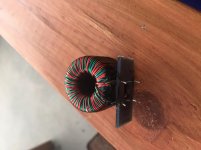
That, i’m not 100% sure. On the pictures, the one that’s sitting on top of the amp is the good one in the same orientation as when i removed it. I checked continuity and i got continuity on the front lefr and back left and front right and back right as we are looking at it. The damaged coil read continuity front left and front right, and back left and back right. When installed on the amp each winding ended on adjecent connected pads.
The good coil, as far as i can tell, 2 windings go on connected pads and cross over to another set of connected pads. I don’t know if that makes sence.
I might have to find a better way to explain it. How is a an filter inductor supposed to go in a circuit? I tried making sense of schematics i saw online, but i’m not 100 percent clear.
Attachments
Post a link if you found a diagram for this amp.
The windings are in parallel when in the circuit. If you pull the good inductor and read continuity to the same inductor terminals (out of the board), you likely have it right.
The windings are in parallel when in the circuit. If you pull the good inductor and read continuity to the same inductor terminals (out of the board), you likely have it right.
Just to clarify, i do not have a schematic for this amp. I was looking at generic class d circuits.
As for the inductor: i took both of them back out measured them and they still measured the same position on the windings and still no short on the “bad one”. I pulled one more wrapp from the windings, but routed it differently then what i has at the beginning. At the beginning i didn’t want to remove too much wiring from the windings, so when i cut it i ended up with the legs of the winding comming out of the center of the core, then flat against the outside of the core and then 90 degree turn to the isolating pad. So the legs (from the same winding) were crossing outside of the core. They wasn’t touching or crossing.
Gave it a shot and cut the windings to were the now come out of the core and straight into the hole on the isolator, so now the legs don’t cross outside the core after that last turn. Put it back on and the amp seems to be working on the scope. I was able to get to 22volts (before clipping)sine at different frequencies and the amp ran cool. I will try it tommorow with a load to see how it does. I think its fixed. But i’ll post tommorow.
Now, i want to learn from this and hopefully help someone else along the way. I’m ruling out a short. Because i moved the inductor all over when it was acting up and no change.
I have a suspicion that the windings crossing after they exited the core were the issue. I thing this way because when i was troubleshooting and the amp would only run good at low frequencies, i was getting close to 40 volts before it would clipp. On my power supply this amp would normally clipp around 22v. Is it possible that the inductor was producing voltage due to the legs of the windings crossing outside of the core, or maybe the uneven windings were trying to act like a transformer? Am i way off? Anyone has an idea?
I’m pretty decent with electronics, but when it comes to inductors and transformers and the like, it’s like some sort of dark magic to me.
Thanks for the help, and i hope someone can benefit from my ordeals.
You may have had the windings cancelling each other out.
You can' leave the shortened windings. The inductance is the square of the number of turns so a slight difference could be significant. You can add to the wires.
You can' leave the shortened windings. The inductance is the square of the number of turns so a slight difference could be significant. You can add to the wires.
Well, i tested the amp with a liad and it’s working like the other working amp. I’m not going to glue down that inductor yet. I’m going to take a shot at rewinding it. Main reason is, it got pretty toasty on me a few times, plus whatever happened to it the first time. When i was pulling the windings, i saw some enamel chipping off. Basically, i don’t trust it. This is more like an educational project for me, so i don’t mind doing a bit of extra work and spending a few bucks if i can learn from it.
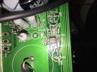
One more question about this amp. This board has slots for 4 rail caps. Iirc this board is the same as the 4201. Both of my boards have only 2 rail caps and diodes installed in place of the other 2. I’m almost sure it is factory, but want to verify if they actually belong in there. The reason is that both boards came from the same source, and there were prior attemps of repair. One of the diodes was shorted, but the amp seems to be running fine without it. That’s the diode on the slot of c128 on the far left. Don’t mind the missing components, this photo is from earlier during the repair.
Again, thanks for the help.
Attachments
I've never seen the diodes in other amps (I've never had to repair a 2301) but the missing caps are common.
I’ll trow one on there just for looks when i order parts. I’m going to try to see if i can use these amps to troubleshoot an mtx 600xd that i have here. The power supply circuit looks the same, so at least i can get that going.
Again, thanks for the help
Again, thanks for the help
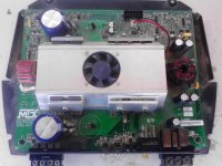
That's an older version of the 4501 that I worked on. It'a an MVP169. Mine is an MVP170 and is significantly larger.
- Home
- General Interest
- Car Audio
- Mtx thunder 2301 output inductor