Dear Nelson Pass:
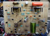
Hello, I want to ask you a big favor: all the schematic diagrams for the Threshold SA/3. It has a DC Offset for 9 Volts on one channel. I already checked all the output transistors and they are not the cause. I have isolated the problem on the driver board for that channel. But the values of some capacitors are not visible. Look, I am in Mexico and unfortunately here it is very difficult to find someone who can repair these units. I love this amplifier and for many years I have tried to repair it but well, in my country I suffer from a lack of audio culture.
I know that a person like you does not have time for a request like this, but even so I try and with great respect I ask if I had to do some paperwork or something else I can do, please let me know.
I thank you in advance for your time to read me.
Sincerely
Chema Duarte
post proper pictures of amp inside, so we can see specifics
it'll help in locating appropriate schm
it'll help in locating appropriate schm
Dear Zed, thank you very much for your very quick response. I get home next Monday and take the necessary photos.
Have a happy new year.
Cheers
Have a happy new year.
Cheers
Dear Dreamth, thank you very much for your quick response and sharing these schematics with me. I see that they are from the Stasis 1, Stasis 2 and Stasis 3 models.
Excuse me for the question: How useful are they for diagnosis for my SA/3 model?
I think that they possibly share the part of the topology, and well I ask you for an additional favor that if you have any advice that you can give me about what part of these diagrams I can use.
Once again, I thank you very much for the time you take to help me.
Have a happy new year.
Cheers
As Zen Mod requested, Please post a series of well-lit, in-focus photos of your amplifier, mainly of the interior, to assist in troubleshooting.
🙂
🙂
Thank you very much for your interest in helping me, look I'm traveling and I return home tomorrow night, I'll send the photos with the detail you mention ASAP.
A happy New Year !
Again , Thank you.
Sincerely
Chema
A happy New Year !
Again , Thank you.
Sincerely
Chema
Dear Mr. Nelson Pass
It is an honor to be able to count on your support.
I really love this amp, because of its exceptional sound and design, and because here in Mexico it's very, very hard to get them. I only knew about you and your amps in magazines from the late 80's and 90's and set out to get one of them.
When you can help me with the schematics it will be great for me. I have tried for 3 years to repair it and I feel confident that it is solved with the support of you and the other members. I was surprised by the kindness of everyone.
Hope it's a great new year!
Sincerely
Chema

post proper pictures of amp inside, so we can see specifics
it'll help in locating appropriate schm
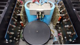
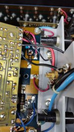
There are two basic versions, the early ones with the output devices cascoded and the later ones with all the output
devices in parallel. I assume yours is the later, but we really need the photo of the front end board in order to
advise where you can make measurements and what experiments will give us more information.

devices in parallel. I assume yours is the later, but we really need the photo of the front end board in order to
advise where you can make measurements and what experiments will give us more information.
Dear All
Hello, sorry for the delay in sending the photos, I was out of town
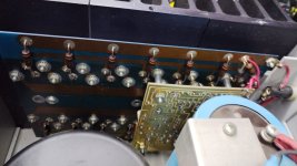
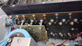
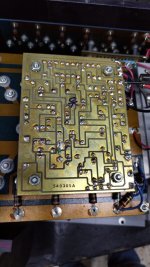
Look, by exchanging the drive between the channel channels and changing the channel the failure, I come to the conclusion that it is the drive card where the failure is.
Please tell me if there are any additional photos missing.
Thank you very much for the support
Chema
Hello, sorry for the delay in sending the photos, I was out of town
Look, by exchanging the drive between the channel channels and changing the channel the failure, I come to the conclusion that it is the drive card where the failure is.
Please tell me if there are any additional photos missing.
Thank you very much for the support
Chema
Attachments
-
 WhatsApp Image 2023-01-10 at 19.03.46 (1).jpeg109.7 KB · Views: 153
 -
 WhatsApp Image 2023-01-10 at 19.03.46.jpeg147.5 KB · Views: 147
 -
 WhatsApp Image 2023-01-10 at 19.03.47 (1).jpeg125.5 KB · Views: 150
 -
 WhatsApp Image 2023-01-10 at 19.03.47 (2).jpeg153.9 KB · Views: 164
 -
 WhatsApp Image 2023-01-10 at 19.03.47.jpeg143.8 KB · Views: 157
 -
 WhatsApp Image 2023-01-10 at 19.03.48 (1).jpeg106.3 KB · Views: 157
 -
 WhatsApp Image 2023-01-10 at 19.03.48.jpeg180.2 KB · Views: 160
 -
 WhatsApp Image 2023-01-10 at 19.03.49.jpeg172.7 KB · Views: 147
 -
 WhatsApp Image 2023-01-10 at 19.04.48.jpeg118.4 KB · Views: 152
 -
 WhatsApp Image 2023-01-10 at 19.05.08 (1).jpeg104.1 KB · Views: 141
 -
 WhatsApp Image 2023-01-10 at 19.05.25 (1).jpeg121 KB · Views: 143
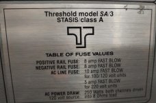
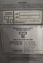
I had the same issue. My was in the differential JFET pair. With that being said, you have a class A Stasis amp with 34v rails. That makes for a great recipe for a 2021 Stasis front end swap designed by the big man up above (post #13)
With your amp, you should be use it with the prescribed values only needing to fabricate a way to get the board onto the output stage and adjust the value of the oscillation cap as needed, if needed.
Let me know if that idea appeals to you and I will pull up some stuff. I will say that my old boards are repaired and I have no desire to put them back in. I originally had 80v rails and actually changed the whole power supply in order to get the rails low enough to accommodate the new front-end design
In that case we are in luck because A) this is easier to fix and B) I made up some new boards
for these.
for these.
Dear All:
Thank you very much for your interest in helping me. Please excuse the delay in answering, because of my work I have to travel constantly (Transportation business)
Please, I ask you not to take it due to a lack of attention from me.
I'm going to review your comments.
Again thank you very much !!
Thank you very much for your interest in helping me. Please excuse the delay in answering, because of my work I have to travel constantly (Transportation business)
Please, I ask you not to take it due to a lack of attention from me.
I'm going to review your comments.
Again thank you very much !!
- Home
- Amplifiers
- Pass Labs
- Mr. Nelson Pass, a support favor