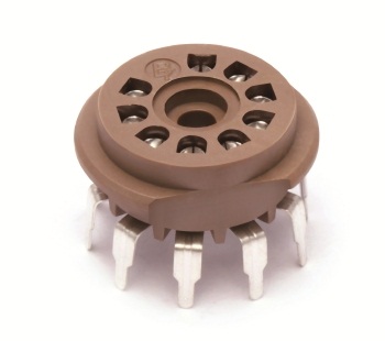
These are the 9 pin PCB-mount valve sockets by Belton. Everywhere I've seen them used in guitar amps (where the valves hang upside down through the bottom of the chassis), they are connected to the PCB just with the solder pins and not touching the chassis. So when you are pulling a tight valve out you are really stressing the solder joints and flexing the PCB. Two questions:
Does anyone ever use the central hole to screw the socket to the PCB for extra support? The hole seems like the perfect size for a standard M3 screw. What else is it for?
Does anyone ever mount the socket right up against the chassis with the mounting hole just large enough for the protruding cylindrical base (around 19 mm dia)? I think if the PCB was mounted to the chassis with 10mm standoffs then this could work. This way the chassis will absorb the pulling force of removing a valve from the socket preventing the PCB from flexing (and avoiding stressing the solder joints).
Does anyone ever use the central hole to screw the socket to the PCB for extra support?
The hole seems like the perfect size for a standard M3 screw. What else is it for?
Tube sockets used to come with a floating terminal riveted to the center hole.
It was often grounded in tuners for shielding.
To relieve solder joint and pcb stress, you really have to use the style with
mounting ears, and bolt these to the pcb before soldering the pins to the board.
See this photo:Photobucket
Attachments
Last edited:
- Status
- Not open for further replies.