I am experimenting with a mosfet source follower output stage. I am using an IRF510 sitting on a current sink set for about 1.2a. I have a question about the output impedance.
From info I have found on the web, Zout should be approximately 1/gm. Datasheets show the IRF510 transconductance (gfs) as 3.5s which should make for a Zout of ~0.3 ohms. However, when I measure the test circuit I get about 3 ohms, 10 times higher.
Can anyone explain the result? What am I missing?
Thank you in advance.
gfs isn't a constant - it is a function of Id, and Vds for lower Vds
look up MOSFET modeling - there should be a ~square law region for some bias conditions, constant die temperature
look up MOSFET modeling - there should be a ~square law region for some bias conditions, constant die temperature
Sure. His result may be OK, for IRF510
Gm = 1.3S at 50V/3.4A
Rds = 0.54 ohm at Vgs=10V
He should use something more robust in case he wants to build a power follower.
Gm = 1.3S at 50V/3.4A
Rds = 0.54 ohm at Vgs=10V
He should use something more robust in case he wants to build a power follower.
The gm is only 1.3S when Id=3.4A.
When the Id is reduced to 1.2A the gm is much lower. Look up the datasheet plots.
If you NEED a lower Zout then you will have to use NFB to divide down the impedance.
When the Id is reduced to 1.2A the gm is much lower. Look up the datasheet plots.
If you NEED a lower Zout then you will have to use NFB to divide down the impedance.
Often the datasheets graphs (if there are any) are hard to read for lowish values of Id.
If you do have a few points or a Gm specified at a particular Id, then you can make a quick **estimate** using the mosfet equation:
Gm = 2* sqrt(Id*K)
From datasheet (or more precisely information above) we have enough info to estimate K
At Gm=1.3, Id=3.4, K works out to be approx. 0.12426
Now that we have K, we can work out the transconductance Gm at other values of Id.
So using the same equation and putting Id = 1.2A, K=0.12426 the transconductance works out to be about 0.772S .....
HTH.
No need to go for global NFB. There is enough NFB in the follower itself. He just may use different part. IRFP90N20D will make very, very low output impedance, e.g. Or something more conventional like IRFP240. IRF510 is no good for a power follower.
Thanks
This is the first time I have posted to this community and I want to thank all for the quick and very helpful responses.
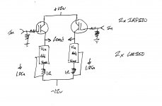
My design experience is with vacuum-state, although I often use SS devices in my projects as current sinks, regulators, and for hybrid cascodes. I wanted to try out a simple class A, direct coupled, no feedback mosfet output stage that I might use after a tube voltage amplifier.
I try to learn as much as I can up front from online and textbook sources, but I learn the most by building and measuring. Hence the attached circuit.
I chose the IRF510 to start with because of it's relatively low input capacitance that I though might be easier for a preceding tube stage to drive.
I attached an 8 ohm power resistor across the mosfet sources as a test load for measurements. To find the Zout I put a potentiometer across the test load and found the value that cut the output in half. That value was about 6 ohms. For simplicity, in my original post I described one half of the output stage responsible for half of the Zout (3 ohms). I found a headphone amp circuit online using a single IRF510 source follower output that reported a 3 ohm Zout so I figured I was in the ballpark.
Thanks to your responses, I have learned how to better predict the Zout from the datasheets. (I should have figured out myself that transconductance varies by operating point. Tubes are the same. Thanks for the reminder.) I will check out the suggested IRFP240 and TRFP90N20D as options for a lower Zout.
Once again, thanks to all.
Paul
This is the first time I have posted to this community and I want to thank all for the quick and very helpful responses.
My design experience is with vacuum-state, although I often use SS devices in my projects as current sinks, regulators, and for hybrid cascodes. I wanted to try out a simple class A, direct coupled, no feedback mosfet output stage that I might use after a tube voltage amplifier.
I try to learn as much as I can up front from online and textbook sources, but I learn the most by building and measuring. Hence the attached circuit.
I chose the IRF510 to start with because of it's relatively low input capacitance that I though might be easier for a preceding tube stage to drive.
I attached an 8 ohm power resistor across the mosfet sources as a test load for measurements. To find the Zout I put a potentiometer across the test load and found the value that cut the output in half. That value was about 6 ohms. For simplicity, in my original post I described one half of the output stage responsible for half of the Zout (3 ohms). I found a headphone amp circuit online using a single IRF510 source follower output that reported a 3 ohm Zout so I figured I was in the ballpark.
Thanks to your responses, I have learned how to better predict the Zout from the datasheets. (I should have figured out myself that transconductance varies by operating point. Tubes are the same. Thanks for the reminder.) I will check out the suggested IRFP240 and TRFP90N20D as options for a lower Zout.
Once again, thanks to all.
Paul
Attachments
I think the sides of Nelson Pass are not bad for the beginning and exactly what you have in mind.
IRFP240 is a good choice.
By the way, I would put the load and power source to the source of Mosfet.
IRFP240 is a good choice.
By the way, I would put the load and power source to the source of Mosfet.
- Status
- Not open for further replies.
- Home
- Amplifiers
- Solid State
- Mosfet source follower output impedence