Hello all,
I am using a simple series MOSFET regulator for my tube amp, to drop some voltage for the phase splitter, from ~480V to 400V.

I wanted to test the setup, and the mosfet blew up a couple of seconds after connecting the HT, although there is no short circuit at the output.
Can anybody help me a little bit to debug this circuit?
Is perhaps the voltage on the gate too high, and that to be the reason why the device keeps blowing up?
Should I consider moving to a higher Vds breakdown voltage device?
Thank you!
I am using a simple series MOSFET regulator for my tube amp, to drop some voltage for the phase splitter, from ~480V to 400V.
I wanted to test the setup, and the mosfet blew up a couple of seconds after connecting the HT, although there is no short circuit at the output.
Can anybody help me a little bit to debug this circuit?
Is perhaps the voltage on the gate too high, and that to be the reason why the device keeps blowing up?
Should I consider moving to a higher Vds breakdown voltage device?
Thank you!
R1 x C10 sets the "soft start" ramp up time, and appears to be 18 milliseconds in the schematic of post#1. Perhaps this is too quick?
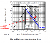
If C3 charges according to I = C x dV/dt , and if dt = 18 milliseconds, and if dV = 400 volts , and if C = C3 = 100 microfarads, then I is in the vicinity of 2.2 amperes during the charge-up of C3.
The power dissipated in the MOSFET is approximately (500v - 200v) x 2.2 amps = 660 watts at the midpoint of the soft-start.
I've attached the Safe Operating Area curve from the IRF840 datasheet, along with a couple of my own annotations. Other diyAudio members may wish to comment upon, and make suggestions about, this plot.
Attachments
I've found the issue, the protection zener put between the gate and source was shot, and when I've connected the HT, it blew the MOSFET, the 400V zener combination, and the 1K resistor.
Replacing the protection diode made the thing work. However I've exchanged the MOSFET to a 2SK2645 device (has VDS ~600V).
Also, I've found that I needed to reduce the 180K resistor down to 5.6K because under load the regulator would not provide enough voltage.
Replacing the protection diode made the thing work. However I've exchanged the MOSFET to a 2SK2645 device (has VDS ~600V).
Also, I've found that I needed to reduce the 180K resistor down to 5.6K because under load the regulator would not provide enough voltage.
Member
Joined 2009
Paid Member
R1 x C10 sets the "soft start" ramp up time, and appears to be 18 milliseconds in the schematic of post#1. Perhaps this is too quick?
I'd increase C10 too, not only to slow down the initial ramp but because it will better shunt noise from the zener stack which likely has a lower dynamic impedance than the 100nF shown.
- Status
- Not open for further replies.