Using the tried and true method as described by nelson pass for matching Mosfets as shown on the left. By using a regulated power supply, taking a mosfet from a batch, setting the pot to obtain a specific amount of current through the resistor and then swapping mosfets without changing any of the settings and noting the differences between the devices...Will the set up on the right give the same results all else being equal? I have a specific reason I want to use the setup at right vs the set up at left.
I want to use a Microcontroller to to test banks of 10 or 12 mosfets at a time. I can program the MCU to pulse each mosfet for a specific duration and then sample the value across the resistor and export it to an Excel datasheet. By using the analog pins of a MCU board such as an Arduino or a Wiring board. I can use the analog pins that have 10 bit resolution to sample the voltage across the resistor as well as control the gate of the mosfet(s). In fact, i could even have the MCU sample data for multiple currents for each bank within milliseconds long before the mosfets have a chance to heatup.
BUT...If the resistor is connected to the drain, then using the analong pins of the MCU gets a bit more complicated as the pins will only handle a 0-5 volt value. I couldn't control the gate and read a value at the same time without the use of some other circuitry to level shift the voltage at the resistor.
Attachments
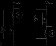
the Vgs vs Id is what you are measuring.BUT...If the resistor is connected to the drain, then using the analong pins of the MCU gets a bit more complicated as the pins will only handle a 0-5 volt value. I couldn't control the gate and read a value at the same time without the use of some other circuitry to level shift the voltage at the resistor.
The righthand diagram measures the Id OK.
How do you measure and/or set Vgs? You have added an extra voltage drop that ruins/subtracts from the voltage set by the pot.
The article I saw in Elektor a few months ago used PWM to derive higher voltages for testing -- but note that you can only get 500mA from the USB bus -- I believe that this is the level NP uses for device matching.
Note as well -- if you "pulse" any node your measurement is going to be affected by device capacitance -- and you have to make sure to synchronously measure V and I.
It gets a little more complicated, but you can use TI's high power/high voltage opamps or something like an LM4780 to generate the muscle for bipolar and mosfet devices.
jackinnj - My intent was merely to have the mosfet ON time be consistent. or i should say more consistent then trying to do it my hand. The so called Pulse could be any duration as long as it is the same for all of the mosfets. I had intended there to be a relay in series with each mosfet and the MCU would cycle each relay on/off in sequence. all of the relays would then be connected to a common resistor of which the Vdrop would be measured across by the MCU.
One relay cycles on, the drop measured, relay cycles off and then repeat going down the line. that way. all of the gates in the block of DUT's are all on and at the same voltage and just the relay in series with the mosfet cycles on/off.
I'm sure there are many ways to do this. I was trying to think of a simple, easy way to automate it a bit without getting to complicated or expensive.
- Status
- Not open for further replies.