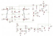
I merged a simple DC detection circuit with a Mosfet power supply switch to create an effective power supply cutoff. I only have a few questions about the circuit, what should the optimum values of R5, R6, R7, R8 be when running off s +/-50V supply, also do you see anything wrong with the circuit.
Attachments
I got the PCB for the circuit made and I'm testing it now and theres something wrong with it. when I short the v+/- rail to the speaker outputs on the board to test the protection, I noticed that the voltage does not drop the 0v but goes up and down from 10v to 0v over and over again. It seems that when the voltage from the PSU drops to 0V the protection circuit thinks that theres no DC anymore so it turns off and detects it again and lets a little voltage through when it's turning the mosfets off. it does this only when you short the PSU's outputs to the speaker (which would happen if the amp fails), if you short the +/- from the bridge rectifier it stays at 0V. how would you fix this problem? 😕
You need to latch the fault status and only reset it when the mains is disconnected and re applied.
This is why i use a microcontroller on my setups. The microcontroller can detect DC and also have a 4 second power up delay on the relay.
This is why i use a microcontroller on my setups. The microcontroller can detect DC and also have a 4 second power up delay on the relay.
Will this mod make the circuit latch till shutdown?
Attachments

Last edited:
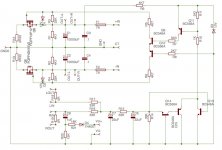
I found away to make it work and not reset, use the fets to short circuit the supply and blow the fuses when DC offset appears, I tested it with 3A fuses does anybody think that a 7A fast-blow fuse could blow up the fets there are 3 in parallel with each other the PNP are rated for 15A and NPN rated for 45A, I don't want to blow the fets. the supply voltage is 50V+/-. the circuit is attached
Attachments
- Status
- Not open for further replies.