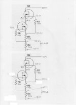
I've got two identical MOS-FET Constant Current Source circuits.
They are designed to provide around 8mA from a 350V supply.
This is part of an Impasse Pre-Amplifier for anyone who is following my queries.
The lower circuit works fine and provides 7.7mA, exactly as designed.
The upper circuit doesn't. It provides 12mA.
Now, is this just a matter of tweeking R5 or do I have a faulty MOS-FET or two ?
Attachments
I don't believe the numbers. If those are really N-channel MOSFETS the gate should always be a couple few volts above the source, which doesn't seem to be the case.
Looking a bit more, and I'm no expert on these things, there shouldn't be any measurable current flow in the gates, so the voltages on each side of the gate resistors should be equal. It's very easy to overvoltage a gate and they have no tolerance for it unless zener protected. Oh, wait, whack me in the head! These are normally on devices. Everything I know is wrong. Still, I don't think current should be flowing in the gates.
edit- it's actually the lower circuit that looks like it's working right if the gates operate a bit negative! The upper doesn't make sense so maybe the part(s) are damaged. I'd want to add some kind of gate protection. Gate voltage can be quite variable, so I'm not sure if you built ten of these circuits that they'd all be close in current value.
edit- it's actually the lower circuit that looks like it's working right if the gates operate a bit negative! The upper doesn't make sense so maybe the part(s) are damaged. I'd want to add some kind of gate protection. Gate voltage can be quite variable, so I'm not sure if you built ten of these circuits that they'd all be close in current value.
Last edited:
Easier: try increasing the source resistor on the higher current one. If you can get the current to drop to where you want it (anywhere around 8mA), your MOSFET is OK, you're just dealing with device-to-device variation.
Cheers SY, I've posted this here instead of the Impasse thread to let some others comment rather than keep bothering you.
Unfortunately the article gives no idea as to how far to vary R5. To halve the 12mA would I be safe trying something like 470R ?
Unfortunately the article gives no idea as to how far to vary R5. To halve the 12mA would I be safe trying something like 470R ?
There isn't an advance way to predict it, since this varies a lot from device to device- that's why I suggested a jig to determine it experimentally. 470R could work, but my gut tells me that 390R would be closer.
edit- it's actually the lower circuit that looks like it's working right if the gates operate a bit negative! The upper doesn't make sense so maybe the part(s) are damaged. I'd want to add some kind of gate protection. Gate voltage can be quite variable, so I'm not sure if you built ten of these circuits that they'd all be close in current value.
Yes, the lower circuit is working perfectly. SY has jumped in, it's his design.
There isn't an advance way to predict it, since this varies a lot from device to device- that's why I suggested a jig to determine it experimentally. 470R could work, but my gut tells me that 390R would be closer.
As the power in the resistor is only about 20mW why not use a 500R trimmer ?
Too late now as I've got the PCB, but I'll try 390R.
As the power in the resistor is only about 20mW why not use a 500R trimmer ?
In theory you could for both CCS, but that runs DC through a wiper at low impedances, which I try to avoid. Unnecessarily fiddly as well. But if you like fiddling, no reason not to.
I might just try a 500R trimmer to ascertain if the circuit is working.
I'm pretty careful with ESD and I've never yet had a component fail during soldering - or unsoldering come to it.
I'm pretty careful with ESD and I've never yet had a component fail during soldering - or unsoldering come to it.
Conrad figured out that these were depletion mode devices.
Even a blind pig finds a truffle every now and then.
I mention protection not so much due to ESD, but to deal with unknown conditions on power up or down. I'd want to watch the Vgs (not that easy to do) during power up to be sure the gates stay safe. Though I'm not a big simulator user, that might be an easier way to check it, assuming a decent model exists.
OK. I'm back at the bench this morning.
Re-iterating, the lower CCS is working as designed.
Using the measurements from the upper CCS I'm calculating that the CCS requires 12mA x 300R = 3.6V across R5 for it to operate.
Transposing Ohm's law, to get the required 7.7mA I should need 3.6V / 7.7mA = 467R
I've just replaced R5 with a 470R resistor and now the current is 10.7mA ????
I've checked, re-checked and checked the PCB again and again. I'll replace the MOS-FETs and see if that makes any difference.
I've removed the MOS-FETs and thought I'd give them a test.
Using a 18V supply and a 120R is series between + and Drain, Source to -.
With no Gate bias the device conducts.
Applying a variable -ve bias to the Gate via a 220R gate stopper, the devices are both turned off with Vg ~ -5V.
So far I would say they are both OK.
However the resistance between Gate and Drain/Source is practically 0 Ohms which would indicate they are goosed ??
However the resistance between Gate and Drain/Source is practically 0 Ohms which would indicate they are goosed ??
That is not an encouraging sign. Since these are cheap, I would not waste time trying to determine good/bad, I'd just replace them.
- Status
- Not open for further replies.
- Home
- Amplifiers
- Power Supplies
- MOS-FET CCS Issues