Hello,
Here is the V2 of my modular TDA1387 DAC, but even this one i dont consider released but a development version which is why im making this thread.
I'll then release the gerber files and anyone can make their own if they want to.

We're using PSU -> cap multiplier -> Jung superreg. For I2S, we have the JLsounds I2SoverUSB board.
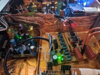
Using 5 x 6 dacs in parallel in little towers, parallelisation averages the currents and improves SNR, but more importantly increases current, meaning we can get away with using a lower value passive resistor, The dac wants to see as close to 0R on its outputs. Also, we dont need further voltage amplification to line level, here i used a 51 ohm resistor.
There's footprints for pin 7 (VREF) decoupling caps but i dont hear a positive difference and some others practice this same method.
Im still troubleshooting some parts though, as simple as everything is i managed to muck it up apparently.
With 30 dacs, current is +-30mA. On 51R that should be almost 1.5v p-p, however on full volume i only get 30mA (what we should get with only one dac). So somehow we managed to break ohm's law here.
I also tried TDA1543 (non A, that one is EIAJ) since they are pin compatible and appear both are I2S. I have some NXP branded ones, but they dont seem to work at all, just get some white noise (although its volume changes slightly with what should be music playing, but its still pure white noise). I tried a lot of combinations according to the connection sheet like left and right justified and different word lengths, but all is the same, so i dont know if anyone else has experience with this..
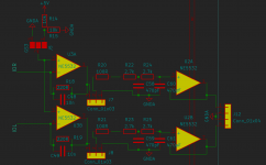
The opamp I/V (passive and opamp I/V is switchable via jumper, for evaluation) also seems to have an inexplicable 1.75V of DC offset and sounds crunchy.
J5 selects what gets connected to the non inverting output. When used with +-15V (like i do), i connect it with GND. The other is just VCC/2 for single supplies.
The feedback resistor is low because there should be a lot of current so we dont need a lot of gain, after that there's the optional buffer (connect 3 and 2 on J7 and J8). Anyway problem happens before the buffer so it doesnt seem to be the issue. Its probably something really silly but i dont see it..

Best regards
Here is the V2 of my modular TDA1387 DAC, but even this one i dont consider released but a development version which is why im making this thread.
I'll then release the gerber files and anyone can make their own if they want to.
We're using PSU -> cap multiplier -> Jung superreg. For I2S, we have the JLsounds I2SoverUSB board.
Using 5 x 6 dacs in parallel in little towers, parallelisation averages the currents and improves SNR, but more importantly increases current, meaning we can get away with using a lower value passive resistor, The dac wants to see as close to 0R on its outputs. Also, we dont need further voltage amplification to line level, here i used a 51 ohm resistor.
There's footprints for pin 7 (VREF) decoupling caps but i dont hear a positive difference and some others practice this same method.
Im still troubleshooting some parts though, as simple as everything is i managed to muck it up apparently.
With 30 dacs, current is +-30mA. On 51R that should be almost 1.5v p-p, however on full volume i only get 30mA (what we should get with only one dac). So somehow we managed to break ohm's law here.
I also tried TDA1543 (non A, that one is EIAJ) since they are pin compatible and appear both are I2S. I have some NXP branded ones, but they dont seem to work at all, just get some white noise (although its volume changes slightly with what should be music playing, but its still pure white noise). I tried a lot of combinations according to the connection sheet like left and right justified and different word lengths, but all is the same, so i dont know if anyone else has experience with this..
The opamp I/V (passive and opamp I/V is switchable via jumper, for evaluation) also seems to have an inexplicable 1.75V of DC offset and sounds crunchy.
J5 selects what gets connected to the non inverting output. When used with +-15V (like i do), i connect it with GND. The other is just VCC/2 for single supplies.
The feedback resistor is low because there should be a lot of current so we dont need a lot of gain, after that there's the optional buffer (connect 3 and 2 on J7 and J8). Anyway problem happens before the buffer so it doesnt seem to be the issue. Its probably something really silly but i dont see it..
Best regards
Attachments
I2S wiring is not really suitable for RF signals. Each signal wire should have its own dedicated ground, with signal/ground pairs loosely twisted and with the pairs separated from each other a bit to help minimize stray coupling between them. Extra series damping resistors on the I2S lines could be put on the dac board to control any ringing. Also best to keep the I2S lines as short as possible. In addition a USB board can radiate RF from the component side which can couple into other dac circuitry. It may help to face the ground plane side of the USB board towards the ground plane side of the DAC board. One example of a setup that worked pretty well is attached.
Attachments
Hello Mark, nice to see you.
I have a quick measurement even of a D1B1 I/V that for some reason worked very poorly (here the output is 98% and only -60db, so maybe the dac currents arent summing like i'd like), probably another one of my faults. But you can see the jitter is very low around the fundamental and the noise floor is almost the floor of the measurement setup, even with just a 32k fft.


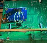
These are good tips, actually i designed the board as a 2x3 header, so each signal line has its dedicated current return path to source ground. But yes i see you noticed i was a bit lazy and just used a single ground and twisted them all together. Anyway it works very well for tda1387, so im not sure that's why the 1543 wont work.I2S wiring is not really suitable for RF signals. Each signal wire should have its own dedicated ground, with signal/ground pairs loosely twisted and with the pairs separated from each other a bit to help minimize stray coupling between them.
I have a quick measurement even of a D1B1 I/V that for some reason worked very poorly (here the output is 98% and only -60db, so maybe the dac currents arent summing like i'd like), probably another one of my faults. But you can see the jitter is very low around the fundamental and the noise floor is almost the floor of the measurement setup, even with just a 32k fft.
Here's what's on the board currently.Extra series damping resistors on the I2S lines could be put on the dac board to control any ringing.
Turning the usb board ground to ground is a pretty good tip, that looks like a nice setup.Also best to keep the I2S lines as short as possible. In addition a USB board can radiate RF from the component side which can couple into other dac circuitry. It may help to face the ground plane side of the USB board towards the ground plane side of the DAC board. One example of a setup that worked pretty well is attached.
Used tda1387 can be sometimes be bad. Makes it easier to figure out if they can be disconnected one at a time. Maybe you could lift one stack at time or something like that? Other than that, I2S signals going to the dac chips can be checked with a 2-channel moderately fast scope. One signal can act as reference to compare the timing of the other signals. A low cost 2-channel 100Mhz scope would not excessive at all hobbyist for dac work.
I changed the I2S lines to each have their own current return since you suggested it, and since the JLsounds board is so conveniently designed for it (as a side note, a sign the designer knows what they're doing imo, i've seen many I2S boards with just one ground connection like 5 pins away). Anyway, it didnt change anything as expected but its good practice to do..
So then i disconnected them all and put them on one by one. Each was perfectly clear, and with each new tower volume went up by the same amount, no matter which permutation i put them in...however the amount the volume went up by was so small, that even with 25 of them contributing +-1mA, i get under <50mV RMS with 51R. The only way i can see it being the chips themselves is if every one of the remaining towers has a couple of dacs in opposite phase or something, im not even sure how that would happen.. I dont know, its really weird. @abraxalito i think you used to piggyback these at some point as well, right?
And then there's the thing TDA1543 doesnt work at all with the same settings, but both should be I2S. Both are time multiplexed, two's complement, TTL logic level I2S. Strange..
It's not even that much money, but i have a bit of expenses now so it always ends up on the backlog
Yup, and this was one of the issues early on, one of the towers had a bad chip and it introduced some garbage, upon removing it was clear.Used tda1387 can be sometimes be bad. Makes it easier to figure out if they can be disconnected one at a time. Maybe you could lift one stack at time or something like that?
So then i disconnected them all and put them on one by one. Each was perfectly clear, and with each new tower volume went up by the same amount, no matter which permutation i put them in...however the amount the volume went up by was so small, that even with 25 of them contributing +-1mA, i get under <50mV RMS with 51R. The only way i can see it being the chips themselves is if every one of the remaining towers has a couple of dacs in opposite phase or something, im not even sure how that would happen.. I dont know, its really weird. @abraxalito i think you used to piggyback these at some point as well, right?
And then there's the thing TDA1543 doesnt work at all with the same settings, but both should be I2S. Both are time multiplexed, two's complement, TTL logic level I2S. Strange..
I wanted to get one of those Hantek USB ones as a starter, at this point there's been many times i just went "damn, wish i had a scope right now" 🙂Other than that, I2S signals going to the dac chips can be checked with a 2-channel moderately fast scope. One signal can act as reference to compare the timing of the other signals. A low cost 2-channel 100Mhz scope would not excessive at all hobbyist for dac work.
It's not even that much money, but i have a bit of expenses now so it always ends up on the backlog
Yes I've been piggy-backing TDA1387 for rather a long time. But I can't figure out here why you'd only be getting 50mV of signal with 30 DACs in parallel. No obvious errors on your schematic except that the 10nF feedback caps around the NE5532 seem a little too large. But that's probably because you have such a small feedback R (200R). I don't think that can explain your results.
To save disconnecting its often the case that a broken DAC can be disabled by shorting its pin7 to GND. That's a method I've used in the past to isolate which DAC is contributing nasty noises.
To save disconnecting its often the case that a broken DAC can be disabled by shorting its pin7 to GND. That's a method I've used in the past to isolate which DAC is contributing nasty noises.
Thanks for your reply abraxalito.
Since you mention pin 7, i guess leaving it floating couldn't be the cause of this right?
Kubelik has pin7 floating and it works pretty good.
Yup, that's what i got with LTspice.Yes I've been piggy-backing TDA1387 for rather a long time. But I can't figure out here why you'd only be getting 50mV of signal with 30 DACs in parallel. No obvious errors on your schematic except that the 10nF feedback caps around the NE5532 seem a little too large. But that's probably because you have such a small feedback R (200R). I don't think that can explain your results.
Here they're on DIP sockets, so its actually easier to just pull them out than fiddle with touching the right leg to gnd.To save disconnecting its often the case that a broken DAC can be disabled by shorting its pin7 to GND. That's a method I've used in the past to isolate which DAC is contributing nasty noises.
Since you mention pin 7, i guess leaving it floating couldn't be the cause of this right?
Kubelik has pin7 floating and it works pretty good.
No, I don't think it can be pin7 floating - all my recent designs have it floating and haven't had a problem with that.
How are you connecting the DACs in the stacks? If just using solder I find that its very easy to have an open circuit which is hard to spot so I'll always run a continuity check on all the connections between the bottom to the top-most DAC in a stack.
How are you connecting the DACs in the stacks? If just using solder I find that its very easy to have an open circuit which is hard to spot so I'll always run a continuity check on all the connections between the bottom to the top-most DAC in a stack.
I agree. Since there was 30 chips with 8 pins, that's 240 connections, its not unreasonable that a few could be wrong. After i made the stacks i checked by touching one end to the very top of the stack, and then other to the DIP leg (to even try to eliminate some trace being cut or whatever). I found 4 which were open and then fixed, but even more surprisingly, i found a few which read like 1.5k, and when you look at it there was just a wisp of solder connecting them.How are you connecting the DACs in the stacks? If just using solder I find that its very easy to have an open circuit which is hard to spot so I'll always run a continuity check on all the connections between the bottom to the top-most DAC in a stack.
Anyway, after fixing all read just the DCR of the test leads. I even used the WBT silver solder for it, just because it flows really well. I guess its just the nice flux core. This was before making this thread, so i guess it wasnt that either.
Im posting the kicad (v6) files in case you or anyone else wants to check them, it was my intention to open source it from the start even though i didnt expect to post this version. I want to contribute to the community and the spirit of experimentation and learning..
As you can see it has a lot of Garman's DNA and some stuff i picked up from you 🙂 overall, its nothing special, other than the stacking trick. Even more reason that its unusual to go wrong
Attachments
Last edited:
- Home
- Source & Line
- Digital Line Level
- Modular TDA1387 development