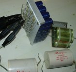
I have modded a couple of preamps by upgrading caps, resistors and diodes with a noticeable difference in sound but when it comes to bypassing caps, I dont hear the difference at all as I did when doing other upgrades, after extensive listening I have tried A/B comparisons bypassed vs none and have not noticed any difference in sound on a couple of different preamps and power amps, I have bypassed caps in the PS and audio path.
I know there is a lot of controversy on the bypassing topic and perhaps some of you can post your results, positive or negative.
I know there is a lot of controversy on the bypassing topic and perhaps some of you can post your results, positive or negative.
IMHO, real bypassing is possible only in DIY units, since industrial ones do not allow enough space for 50...100uF polypropilene shunts. 0,1...1uF shunts can not serve as audible measures, they can only improve or make worse high frequency oscillation artefacts, visible at square wave tests.
I find the biggest differences when bypassing the 20,000µF main filter caps in power amplifier power supplies with caps in the range of 22F~100µF, and a lot less of a difference in preamp supplies (which are generally regulated anyway).
The next biggest change I hear is in signal coupling caps when using film bypass in the range of 0.01µF~0.1µF in parallel with electrolytics in the range of 10µF(typical input cap) ~470µF (typical feedback cap) or so.
The first change makes the bass sound 'tighter', the second makes the mids and HF sound more 'detailed'.
Obviously, if you like 'warm' sounding bass and 'soft' sounding highs you may want to listen to the result before making any permanent changes.
motor start (for lower voltage) and motor run (for higher voltage) capacitors.
Don't use the electrolytic type.
Don't use the electrolytic type.
but when it comes to bypassing caps, I dont hear the difference at all as I did when doing other upgrades, after extensive listening I have tried A/B comparisons bypassed vs none and have not noticed any difference in sound on a couple of different preamps and power amps, I have bypassed caps in the PS and audio path.
I think lot of information needs to be provided. Can you post Circuit diagram,PCB Layout pics and modifications on it?
Here is my standard set of important caps for Zen-like SE class A designs. Main output cap is from low-ESR electrolytics (solid electrolyte), 68uF polypropilene shunt to it, 56uF polypropilene shunt at power rail after virtual battery circuit, 50uF mylar shunt for power rail before the virtual battery.
All this makes sense if one intends to get close to tube-like SE sound.
All this makes sense if one intends to get close to tube-like SE sound.
Attachments
Last edited:
- Status
- Not open for further replies.
- Home
- Amplifiers
- Solid State
- Mods and bypassing caps in amps and preamps
