I've recently been working on an old Marshall AVT 50. I'm planning to change :
1. Add a 0.68uf cathode bypass capacitor to R29.
2. Replace R32 with a 100k resistor.
These two swaps would increase gain from the 12AX7 .
Then I planned to :
3. Replace R72 with a 33k Resistor.
4. Replace C83 with a 470pf capacitor (treble) and replace C78 (bass) and C79 (mids) with 0.022uf CDE film types.
There is some clipping LED's labeled LED 2, LED 3, LED 5 & LED 6. I was wondering, would it be ok to remove LED 2&3 and replace with jumpers and then replace LED 6 with 1N4007 diode. Then, replace LED 5 with wires going to a On/off/on toggle with a different diode arrangement on the switch? Example being one 1N4007 in the middle, two 1N4007 up, and a LED for the down position?
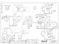
For the record, I am aware amps contain high voltage. I am safe, and take all precautions while working inside the amp. I have provided a schematic of the preamp section for reference.
1. Add a 0.68uf cathode bypass capacitor to R29.
2. Replace R32 with a 100k resistor.
These two swaps would increase gain from the 12AX7 .
Then I planned to :
3. Replace R72 with a 33k Resistor.
4. Replace C83 with a 470pf capacitor (treble) and replace C78 (bass) and C79 (mids) with 0.022uf CDE film types.
There is some clipping LED's labeled LED 2, LED 3, LED 5 & LED 6. I was wondering, would it be ok to remove LED 2&3 and replace with jumpers and then replace LED 6 with 1N4007 diode. Then, replace LED 5 with wires going to a On/off/on toggle with a different diode arrangement on the switch? Example being one 1N4007 in the middle, two 1N4007 up, and a LED for the down position?
For the record, I am aware amps contain high voltage. I am safe, and take all precautions while working inside the amp. I have provided a schematic of the preamp section for reference.
Attachments
I've posted it there. Not a difficult to answer question. Just wanting to know if I can remove the LED's in circuit and replace with a jumper to clean up some of the distortion from the LED clipping.You'd get more answers if this post was in the Instruments and Amps Forum.
You will get a minimal gain increase, best case 2X, barely worth the soldering/desoldering effort.I've recently been working on an old Marshall AVT 50. I'm planning to change :
1. Add a 0.68uf cathode bypass capacitor to R29.
2. Replace R32 with a 100k resistor.
These two swaps would increase gain from the 12AX7 .
This will increase low mids, maybe making sound muddier, not bassierThen I planned to :
3. Replace R72 with a 33k Resistor.
.
minimal increase of high mids4. Replace C83 with a 470pf capacitor (treble)
Minimal sound change.and replace C78 (bass) and C79 (mids) with 0.022uf CDE film types.
No, you are shorting Audio there.There is some clipping LED's labeled LED 2, LED 3, LED 5 & LED 6. I was wondering, would it be ok to remove LED 2&3 and replace with jumpers
You will have a strong signal loss, with no sound improvement.and then replace LED 6 with 1N4007 diode.
You are replacing a 1.9V diode with a 0.65V one.
Again strong signal loss.Then, replace LED 5 with wires going to a On/off/on toggle with a different diode arrangement on the switch? Example being one 1N4007 in the middle, two 1N4007 up, and a LED for the down position?
In sum, all these mods give minimal change and all in the wrong direction.
I suggest you build a pedal which can add as much gain as you wish, easily 10-20X , as many diode combinations as you want, and properly compensate for the inevitable signal level losses.
Leave amp as is.
Unfortunately leaving as is isn't an option as I've already pulled all the signal Path Caps and the resistors I planned to change.You will get a minimal gain increase, best case 2X, barely worth the soldering/desoldering effort.
This will increase low mids, maybe making sound muddier, not bassier
.
minimal increase of high mids
Minimal sound change.
No, you are shorting Audio there.
You will have a strong signal loss, with no sound improvement.
You are replacing a 1.9V diode with a 0.65V one.
Again strong signal loss.
In sum, all these mods give minimal change and all in the wrong direction.
I suggest you build a pedal which can add as much gain as you wish, easily 10-20X , as many diode combinations as you want, and properly compensate for the inevitable signal level losses.
Leave amp as is.
I'm going to use a 10uf as a cathode bypass capacitor. I'm still planning to swap C83 and R72. I've actually ordered Mojotone Dijon caps with the correct ratings to replace them .
For the LED clipping circuit, what would be the correct way to remove LED 2 and LED 3?
I've I have a clipping circuit using multiple 1N4007 I can make up the voltage difference between the LED and the diode, correct?
For example, if I had 31N4007 on LED 5 that would be 1.8v and if I had 4 on LED 6 that would be 2.4v meaning no signal loss, as it would be more then what the LED produced?
Also, it's not the signal loss I'm worried about. I want to remove some of the harsh clipping diodes distortion from the O/D channel.
To soften the clipping place a variable resistor in series with the two diode sets. Since you are mounting a toggle, you might as well mount a pot/trimmer instead and have a wider range of adjustment. Linear or log would give a different feel for the control range of the clipping. Experiment. 1K, 2K and 5K values depending how clean you need it.

If you already decided what to do, not sure why are you asking here.
Replacing 3 series diodes instead of a single Led means no practical change in sound, they are all clipping diodes, all as harsh.
But hey, now that you are halfway across the river, go ahead.
Then YOU tell US 😉
Replacing 3 series diodes instead of a single Led means no practical change in sound, they are all clipping diodes, all as harsh.
But hey, now that you are halfway across the river, go ahead.
Then YOU tell US 😉
- Home
- Amplifiers
- Solid State
- Modifying cheap Amp