Hi, I'm working on a vintage synthesizer circuit requiring a pair of 1960 Triad TY-30X transformers. I've sourced a pair for reference but can find no more, and as this is a project others might enjoy (at least in the electronic music field) I was hoping someone here might know of a modern equivalent. I know nothing about transformers. It's used to drive spring reverb units so if this transformer has any limited frequency range or specific sonic characteristics the replacement must also have them. I'm a sound and music lover; I don't know the electrical side but I can assemble it and use it well if the parts are correct.
Triad TY-30X
Primary 1: 100R center-tapped
Secondary: 4R and 8R
2 watts
40Hz-10KHz
This Magnetek part appears to be similar or the same, can anyone confirm?
Buy Now 5950-00-911-9549 from Lintech IS09001:AS9120 Trusted Distributor
This is the original circuit in which it is used:
http://www.synthfool.com/docs/Buchla/Buchla_190.jpg
which is part of this:
Buchla 100 Series | Vintage Synth Explorer
I'm really hoping to keep the original sonic character which is a very attractive aspect of the system. Thank you for any input, it is greatly appreciated.
Here is my project page, for reference:
ebolatone: Buchla 190 Dual Reverberator DIY
Have you considered driving the reverb with a small power opamp?
The transformer would only make a difference in the sound if it were being overdriven and saturating.
Typically this would not be the case much under normal use and a small power opamp should readily drive it cleanly.
jer 🙂
The transformer would only make a difference in the sound if it were being overdriven and saturating.
Typically this would not be the case much under normal use and a small power opamp should readily drive it cleanly.
jer 🙂
This is a discrete circuit and system and its sonic character is the reason for its reputation...we are attempting to clone it as exactly as possible. There are already plenty of modern equivalent spring reverb circuits and modules available and they all sound different (and some are extremely nice but not exactly this). Thanks though..
http://www.youtube.com/watch?v=aT_5L5UPNRc
http://www.youtube.com/watch?v=aT_5L5UPNRc
Last edited:
You are running DC through the primary on this design, which will effect the performance of the transformer, especially at LF. IF the core is gapped, then the effect is minimized.
The other issue is that the tank you buy today will not be the same as the tank from the 60s or 70s. You'd want to know what the input Z for the tank you are buying is, and then match the transformer to it. You need to know the signal level on the primary, and the voltage max and input Z and those things will help you pick the ratio for the transformer you need.
The site you linked did not have good specs shown. So, it's impossible to tell what it is exactly.
The original Triad catalog page with specs would be useful.
This looks basically like a 1:1 low Z transformer.
The spec you quoted doesn't quite make sense. 1:100 ratio and
a secondary of 4 or 8 ohms? Something is not adding up here.
Keep in mind they may have just used something they had on hand (literally) or something that was cheap, or both.
Quite frankly, the reverb circuit is the least of your concerns in cloning a Buchla.
Fwiw, transistors today are going to behave and perform rather differently than the ones that were used in the original Buchla. It will almost certainly sound somewhat similar but not exactly the same. Think of it like trying to clone a vintage guitar or vintage guitar amp. You get something close, but not exactly the same. Then there is the issue of the caps... I see some tantalum caps, are you going to use tantalums?
EDIT: Just noticed, they used a 2N3055 to run the reverb tank! So, a boat load of current through the transformer. Imo, really really not good design. For this cap coupled ("parafeed") makes a lot more sense. They might have needed a big step up in voltage to run that tank?? That seems odd to me also... remember this was not a terribly successful company.
EDITED EDIT: No, imo, you can not sub a TL071 for a 741 and get the same results. Best buy some old 741s. They can be had. For starters the TL071 is a JFET input amp and sounds VERY different. You might *like* it, but then you might prefer changed a whole lot of other things, and *like* them too. Consider other bipolar opamps. The 4558 is fairly ubiquitous today, and used in a lot of things like effects pedals, and is all bipolar. At least build one module up with the 741s and see how it sounds then compare. Sockets are your friends here. 😀
Last edited:
One of us cloners phoned CBS and got the specs on the reverb tank used in the original module; the modern accutronics equivalent (type 4) has been used to good effect (no pun intended...well, perhaps a little) in at least one owner's system. It is indeed an 8 ohm (input) tank.
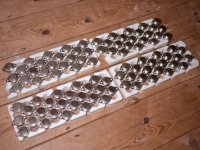
This eBay sale lists some specs and also has a photo of the transformer with some data written upon it:
"100 Ohm CT to 4 or 8 Ohm speaker at 2 Watts."
NEW Unused Triad TY 30X 4 8 OHM Output Transformer F OLD HAM Radio Audio AMP | eBay
I agree, it may or will not sound exactly the same, but we're trying. It's filled with tantalum caps and I'll definitely be using them in my build. I attempt to stay as close to the originals as I can. Some people are happy using 2N390X transistors in place of the 2N3565/2N4248 etc. and the circuits work, but I try to use originals just in case there is some 10% factor which would become clear in a direct comparison.
Yes, the original 190 used T05 can 2N3055 mounted and heat sunk on the PCB. I cannot source any so I'll be using MJE3055 TO220, also heat sunk on the PCB. One more increment which may alter the sound.
My notes on 071 substitution are for those who might wish to try. I value the 741 for its particular dirt; I'll be modifying the Gates which use them to the earlier fully-discrete 110 version. I definitely use IC sockets!
Thank you for your reply and insight!
T05 can 2n3055 - do you mean T03.
They are very easy to source.
Here are over a hundred of them for £2 on E-Bay.
They are very easy to source.
Here are over a hundred of them for £2 on E-Bay.
Attachments
Last edited:
bear, here is a catalogue page including it:
http://www.triadtransformers.com/images/bigArchive/TR-61%20pg-010.jpg
Output and driver transistor transformers: High level
Primary matching impedance: 100CT
Primary current: 100ma
Maximum level: 2W
DC resistance Ohms DC: Primary 8 Ohms; Secondary: ?
The Triad history page says they were purchased by MageneTek so perhaps the item listed in my first post is a genuine substitute.
KatieandDad: T05 style 2N3055 were used in the original with those small "crown" heat sinks (Hatfield #207, discontinued, to be exact). I've seen the T03 and with a heat sink they're too large for the 4" x 6" PCB area with which I have to work (it's also a dual circuit, so two per PCB). Thank you!
From the original module:
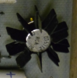
190 Parts 2N3055 TO5 Can by mpeake, on Flickr
http://www.triadtransformers.com/images/bigArchive/TR-61%20pg-010.jpg
Output and driver transistor transformers: High level
Primary matching impedance: 100CT
Primary current: 100ma
Maximum level: 2W
DC resistance Ohms DC: Primary 8 Ohms; Secondary: ?
The Triad history page says they were purchased by MageneTek so perhaps the item listed in my first post is a genuine substitute.
KatieandDad: T05 style 2N3055 were used in the original with those small "crown" heat sinks (Hatfield #207, discontinued, to be exact). I've seen the T03 and with a heat sink they're too large for the 4" x 6" PCB area with which I have to work (it's also a dual circuit, so two per PCB). Thank you!
From the original module:
190 Parts 2N3055 TO5 Can by mpeake, on Flickr
Last edited:
(Squints at schematic, both drawings...compares hand-written "3"s and "5"s...searches the net for 2N3053...)
You are correct! Dang, thank you, very much...that was a deal-breaker right there...I should have known something was wrong when I found no trace of 3055 in can form...Mouser have the 3053, TO-39 all day long. I thank you. (The rest of the components are clearly visible and values identifiable on the PCB photo I have, thankfully...)
You are correct! Dang, thank you, very much...that was a deal-breaker right there...I should have known something was wrong when I found no trace of 3055 in can form...Mouser have the 3053, TO-39 all day long. I thank you. (The rest of the components are clearly visible and values identifiable on the PCB photo I have, thankfully...)
Last edited:
You should be ok with the xfmr as long as the quiescent current sits about 50ma... which is fairly likely the way it was set up... I think the original xfmr has more bandwidth, but the tank coil doesn't care as it is not a wideband thing anyhow...
Pretty wild that anyone would want to clone a Buchla these days... you know they were not held in high regard when they were contemporary? My recollection is that they were considered not terribly stable and somewhat unreliable, but this is an old faded recollection.
_-_-bear
Pretty wild that anyone would want to clone a Buchla these days... you know they were not held in high regard when they were contemporary? My recollection is that they were considered not terribly stable and somewhat unreliable, but this is an old faded recollection.
_-_-bear
Thank you...the Buchla 100 is revered due to its discrete circuity versus many designs, Buchla and otherwise, which followed, utilizing 101, 301, 741, and other limited opamps. Yes, these earliest oscillators were unstable and didn't track, and neither of those things is of any importance to me whatsoever in terms of the soundscapes it may produce. I have modern designs which are closer to digital in terms of accuracy, for when that's important. Peace! I very much appreciate the insight shared here.
Magnetek no longer deal in transformers; Triad say no equivalent and $2500 to remanufacture IF the documents exist. Sigh.
Short answer: those Magnetech transformers you linked to are fine.
Use them if you can get them.
Slightly longer:
being "from that era" (ahem !! 🙁 ) I instantly recognized the circuit type.
It's simply a late 60's "state of the art" small 1W power amp, single ended, (obviously Class A), transformer coupled .
Even without reading the vintage (Triad or whatever) specs, the modern ones fill the bill:
1) max power 2W
2) 100mA "Winding Operating Current" which means it's *meant* for Class A so certainly must be properly gapped.
And yes, that being a "max" value, using it around 50mA idle would be a sensible choice, as was properly said above.
3) 100 ohms to nominal 4 ohms input tank impedance sounds about right, and in fact is what a late 60's Engineer would specify if he were asked to design an SS equivalent of the typical 12AT7 driven reverb of the day.
4) a small detail which should clear many doubts: this *is* a CBS product, meaning Fender, meaning it would *very probably* use the same tank as used by the thousands by other Fender products, if at all possible.
5) agree that although it might be replaced by a chipamp circuit (think TDA20xx) , sound would not be the same:
a) very high internal impedance from the 2N3053 collector vs. very low from a chipamp
b) I assume that although it *should* not be overdriven, there is a distinct possibility of this happening, and if so , such clipping wpould sound *very* different in the different type amps.
c) a simple Op Amp (the typical TL072) would be much weaker (just a few mW) than either tha single ended or chip amps.
They are barely adequate in normal use, go figure .
Thank you SY and JMFahey. I appreciate it. I'll keep after the Magenetek component. Yesterday I spoke with Hammond and they recommended I look at two of their parts:
The 146E is 700mw instead of the 2W listed for the Triad but is possibly the same:
Hammond Mfg. - Chassis Mount Audio Transformers - (140, 143-146 Series)
This 119DA might substitute on the version of the specified reverb tank with a 600R input?
http://www.mouser.com/ProductDetail/Hammond/119DA/?qs=%2fha2pyFadug6Ig uncpFHGEtTF2WQVLi2NXYrlHd4qzQ%3d
The side going from the circuit to the tranny requires a 100R center tap, but the Accutronics reverb tank model can be any of several possible impedances (8R, 150R, 200R, 250R, 600R, 1475R) so a 100R CT 2W with one of those Primary impedances should be a step in the right direction?
Last edited:
Sorry but the 146E won't do.
The main problem is not power handling but DC current through primary, in this case limited to worst case 14mA (so probably it wouldn't be advisable to go over 7 ma idle)
The 119DA does not specify DC current and the suggested use means AC duty only, so I think you will continue your quest.
It's an obsolete and dated way of doing things, (Class A single ended transistor power outs) so I'd sugget you search surplus stuff stores, besides current productas ones.
Or maybe you can salvage something suitable from , say, junked 60's table radios or record players.
Or consider winding your own.
Search for "driver transformers for VOX amps" , in the late 60's that was a standard way of making power amps, there's some dedicated Forums discussing them and even suggesting ways (windings/wire/core data) to "roll your own".
Your main problem lies in the primary and core gapping, because of strong core saturation by DC, then you can mod the secondary for any impedance you wish.
So much for asking a manufacturer 🙁
I'm happy to learn that it's a single-ended Class A circuit. I've already exhausted my usual surplus sources and they didn't have any further ideas. I may have to wind my own, but that's another large set of "what do I need and how do I do it" questions...I didn't realize that this simple circuit would put me so far out there asking for help. I am grateful for the input and education. I'll keep hammering away looking for a source...
I'm happy to learn that it's a single-ended Class A circuit. I've already exhausted my usual surplus sources and they didn't have any further ideas. I may have to wind my own, but that's another large set of "what do I need and how do I do it" questions...I didn't realize that this simple circuit would put me so far out there asking for help. I am grateful for the input and education. I'll keep hammering away looking for a source...
I suggested Edcor because their setup charges for one-offs is quite reasonable, and their prices are attractive.
- Status
- Not open for further replies.
- Home
- Design & Build
- Parts
- Modern equivalent of 1960 Triad transformer?