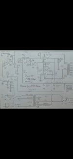
Good evening all~ I just came into this cute little amp, & after much searching online for possible & necessary alterations to make this a guitar growler, but could come up w/only this schematic,
Having my tech just do his thing & not take it further than simply functioning well, is like bringing a Harley to a lawn mower repair guy. Is it possible for some of you kind folks to chime in with 'must do' value alterations to make this 2xEL84, EZ81, 6EU7 into a little monster.... Would immediately having him wire it for a 12ax7 or the gainy & popular Vox EF86 preamp tube be a good start? Then, what more could be swapped out for different values to make it into a guitar or harp that screams, & something more suitable for RnR than playing my dad's olde '78's through. I realize it might sound like a heap of work for ya'll, but I only know basic electronic & can follow a schematic, but have never done it myself,,, I simply want to hand it over to my tech, as I'm just an end user.
Enclosed is a chassis shot & an original schematic for you generous consideration...
Thnx in advance~
Attachments
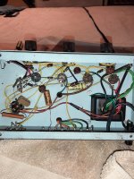
Looking inside I see a wax cap in the center. That almost certainly will be leaky by now. But other than that and maybe some fresh filter caps, Have you tried playing through it? The phono input is intended for ceramic cartridge and so doesn't have a big RIAA circuit. That would be a lower gain input. The MIC input has an xtra gain stage - a higher gain "channel". You might find the thing sounds awesome just as it sits there.
6EU7 is easy enough to come by and is a good tube, I see no reason to yank it right away.
Is your tech competent? Why not discuss it with him?
If you bought an old Harley, you would owe it to yourself and to your hog to ride it and see how she goes. You wouldn't decide on new forks, a different head or god knows what all before you even see the thing.
The 6EU7 has the same characteristics as the 12AX7. The main difference is that the filament voltage of the 6EU7 is 6.3 V only (and it has a different pin-out).
What surpises me is that the anode resistor of V1a is connected straight to the rectifier. Maybe this was done to squeeze some more amplification out of V1a. I would connect it at C1c so as to reduce hum (power supply ripple) as much as possible.
I think that the cathode resistor of V1a is only 430 Ohm to accommodate the low impedance microphone input. If you are not going to use that input (guitars need the high impedance input) than I would change the 430 Ohm resistor for a 2K2 one and bypass it with a capacitor (like 22uF) to get more gain.
The value of the cathode resistor of V1b is only 100 Ohm according to the schematic. I would think this can't be true so you could check this (maybe there is an extra resistor between the cathode and this 100 Ohm resistor). Like with V1a, I would think 2K2 (or 2K7) is a better value. If you do this, than probably you have to higher the value of the (now 35K) feedback resistor also so as to keep the amount of feedback the same.
The two 330K resistors at the grid of V1b are there to prevent shunting all signal to ground when one of the pots is at minimum. But the price for this is that the signal gets halved. So if you are not going to use the phono input anyway, than removing the 330K between the mic pot and the grid of V1b will give you more gain.
The value of the grid resistor of V3 is 2M2. The maximum value for this resistor is 1M according to the datasheets. But probably it is 2M2 in this amplifier in order to get enough voltage swing. The phase inversion is a bit unusual; the voltage for it is developed over the 2K2 resistor by the varying screen grid current of V2.
Adding grid stoppers (1K) at the grids of V2 and V3 could be an improvement.
Attachments
Last edited:
Gotcha!! Well, I just it today, finally was able to plug it in, (only after knowing that it was safe to do so) & it's got a good sound at the rather low volume I was able to achieve, & being a courteous neighbour,, but in the next day or so, I should have chance to crank it & see... As far as the preamp tube goes, does the 6EU7 stack up gain factor wise to the 100 gain factor of a 12ax7?
Thnx
Thnx
That is not a Factory schematic but drawn by an amateur, so errors are possible.
Definitely V1a needs a hum free supply, so connect it to same place as V1b
V1b cathode will also need higher than 100 ohm, try 430 ohm as in V1a and even 1k (or 1k5-2k2) on both.
Aim at plate voltage between 50% and 75% of feed rail voltage.
The rest of the circuit looks reasonable, you don´t have extra gain on tap to go crazy but in any case circuit as-is is reminiscent of early Fender Tweed amps ... not bad at all.
Follow Enzo´s advice on old caps and everything else and thanks PFL200 for the complete schematic..
Bypassing cathode resistors with 10uF x 25V caps will rise gain .
Crank it. It is a "Tweed" of a different flavor.
If you truly want The Amp Of Your Dreams, don't start with grandfather's low-price PA.
If you truly want The Amp Of Your Dreams, don't start with grandfather's low-price PA.
A bit strange that a PA amplifier has a phase inverter which, if I'm not mistaking, only works good if the power stage stays in class A.
- Home
- Live Sound
- Instruments and Amps
- Modding a Davis Model 106 P.A. Amp....