Picked up a Crate VC508 (Simple 12AX7/EL84 5W combo). It's OK. Read about a few mods, specifically removing the crap SS buzz circuit. So I did it, as per this post:
UG Community @ Ultimate-Guitar.Com - View Single Post - Crate VC 508
Also used this for reference:
GuitarNuts.com - Crate VC-508 Improvement
Schematic here:
https://www.dropbox.com/s/jy01xhqrtpuw3g7/scm_electronics_vc508_sch.pdf
Now, I have a pretty heavy 60hz sharp buzz/hum. It's a pretty simple circuit, not sure where it's coming from, but here are some things I've tried:
-Unplugging the heater wires results in an immediate drop in buzz. There's still some, but it's significantly less. Over several 10's of seconds, everything drops off as the heaters cool.
-Removing the 12AX7 preamp tube removes all buzz. Volume knobs have no impact on the hiss that remains.
-Volume pots for both stages affect the buzz. I figure this has to mean it's pre-amp related.
-Despite pins 4&5 being driven by the same line, there is a 0.1ohm resistance between them. Is this significant?
-I am certain it's a 60Hz buzz, not 120Hz.
-Measuring voltage (ie - touching DMM leads) between ground and Pin 2 on the 12AX7 reduces the hum.
-Measuring voltage (ie - touching DMM leads) between ground and J6 (the 272V AC feed) increases the frequency of the buzz to 120Hz (I'd guess).
I have not tried a new 12AX7 yet. Can anyone confirm whether or not a bad tube behaves in this way (ie - buzz responds to volume control etc)?
I keep reading about "balancing filament windings" etc. Since the 12AX7 is NOT using a grounded center-tap, how would I do this?
As I was typing this, I realized that "measuring" the voltage of Pin 2 and J6 is essentially putting a large-value resistor there. Does this mean it's ground related?
Thanks for any and all help!
A schematic of how the amp is now would help. It's a bit of a puzzle now.
I understand that you bypassed the ss input circuitry and the input goes via a 47k resistor to the grid of the first triode section. Did you leave the 100k resistor to ground? (I would change it to 1M as this is the load of your guitar pickups, but that could be a later tweak)
Do you have shielded cable from the input jack to the 12AX7?
Is it a shorting jack? (without cable the input shorts to ground)
How are the heaters connected now? AC? Traces on a pcb or twisted wires? Often you see either a humpot connected to the 6,3V with the wiper grounded, creating a pseudo center tap. Two 47 or 100 ohm resistors can be used as well.
I plan on changing the 100K to 1M, but have put it off until the buzz is gone 🙂
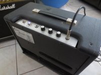
The wires are NOT shielded. Pic below.
Here is what I done. Red X's indicate that I've removed that part - either cut the wire, cut the chip out, etc.
The input jack is a NC jack. I've tested that it is indeed shorting. The buzz doesn't change with guitar plugged in or not.
EDIT: The heaters are AC. 4&5 are tied and connected to one of the transformer outputs, pin 9 (CT) is the other output. I believe this means the 2 heaters are connected in parallel? Not sure what the proper term for this is, most seem to be "center tap grounded", this is not.
https://www.dropbox.com/s/pra2ii6e72yktlv/mngnt_vc508_schematic.png
Last edited:
 The best place for this thread is in Instruments & Amps where it is likely to get more responses. Please see the forum sub headers for the best place to post specific threads.
AndTubes / Valves All about our sweet vacuum tubes 🙂 Threads about Musical Instrument Amps of all kinds should be in the Instruments & Amps forum
Instruments and Amps Everything that makes music, Especially including instrument amps.
Mod, my apologies, thanks for the move.
Thought I'd send an update.
Replaced the 12AX7, did nothing. Thought some more about it.
--
Figured out it was the "gain" aka first stage pot picking up the AC anode wires pre-rectifier. I've moved some of the wires around and significantly reduced it, but it's still bad. I'm going to relocate the rectifier circuit somewhere further away.
Hi,
For a test try shorting the input and see if the buzz goes away.
The input is shorted by default. As a test, I plugged in a cable and played with the open end - no change in sound whatsoever. This led me to believe the noise was caused between the 2 stages of the 12ax7 tube - something on pin 7, not pin 2.
Hi,
I do not know but the sound in the video it's sounded like a an open input. Did you double checked the input to make sure it is connected as you showed in the revised schematic?
I do not know but the sound in the video it's sounded like a an open input. Did you double checked the input to make sure it is connected as you showed in the revised schematic?
The input is shorted by default.
Only if the input jack and its connections are all working 100%.
Never think up reasons not to check something.
VC 508 Mods
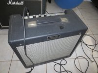
Great info on possible mods for the VC 508. I modded mine by simply placing the brains of the VC in a Fender Blues Jr. I bought on ebay for $60 and added a Celestion G12 M Greenback I had lying around. I love the sound and pure power of this little monster.
Great info on possible mods for the VC 508. I modded mine by simply placing the brains of the VC in a Fender Blues Jr. I bought on ebay for $60 and added a Celestion G12 M Greenback I had lying around. I love the sound and pure power of this little monster.
Attachments
Agree, that is an interesting article. 2 things I suggest checking out. Elevated heater voltage supply, and shielding the input wire. You have an isolated jack which is good. The shield wire only gets terminated at one side as close to the cathode bypass cap of the V1 stage as possible on its negative side. I think this is where it may be tricky cause you probably have a signal ground trace directly on PCB mount jack, so possibly terminating the shield on that point may work but you will have to test.
Elevated heater supply: check MOD 102 kit schematic
Have fun
Elevated heater supply: check MOD 102 kit schematic
Have fun
- Status
- Not open for further replies.
- Home
- Live Sound
- Instruments and Amps
- Modded Crate VC508 - Heavy 60Hz buzz