Since I now have time to catch up on all the things that needed ... time.
I am no EE, far, far from it, but I am trying to learn at least some basics. My eyeballs hurt from constant staring at the computer screen. A couple buds at diymidwest helped me bunches building a 4s Universal tube preamp 4S Universal Preamplifier for 12A*7 Tubes. The build is here. 4s Universal tube pre — MAC/DIY While it allowed much tube rolling, it was pointed out how it was 'one size fits all' and while it might be optimal for a few tubes, for most tubes it probably was not. To that end, I was urged to optimize the 4s Universal for a single tube. The 12au7 it is.
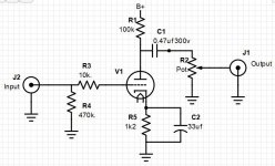
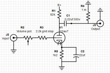
Since I am but a newb, the cap/resistor values were suggested to me by the place I buy almost all the tube stuff, and moving the volume potentiometer to the input was suggested by everyone. This is the before and after. First diag is the original 4sUniversal, modded is number 2. After adding the 250k. of the potentiometer and 2.2k. stopper, I did not have the correct size smaller resistor to get exactly a 1m. grid leak so I had to put a 1m. in there.
First time ever doing a load line so this may not be correct, but if it is, the resistor/cap values may be way off.
For the load line, B+288v/82k+1.2k=3.46ma
For the cathode load line 2v/1.2k=1.67ma and 6v/1.2k=5ma
Way down in the lower left-hand area you will see Light green;load line, pink;cathode load line, and darker green;operating point. Also extended the cathode load line past -11v, which is the half-way point between grid voltage curves-22v and 0v. For a center bias, isn't this what I should be aiming for in an audio preamp? Using -11v as center bias and 288v yields the blue line, which I'm guessing is approximately where the load line should be?
I am no EE, far, far from it, but I am trying to learn at least some basics. My eyeballs hurt from constant staring at the computer screen. A couple buds at diymidwest helped me bunches building a 4s Universal tube preamp 4S Universal Preamplifier for 12A*7 Tubes. The build is here. 4s Universal tube pre — MAC/DIY While it allowed much tube rolling, it was pointed out how it was 'one size fits all' and while it might be optimal for a few tubes, for most tubes it probably was not. To that end, I was urged to optimize the 4s Universal for a single tube. The 12au7 it is.
Since I am but a newb, the cap/resistor values were suggested to me by the place I buy almost all the tube stuff, and moving the volume potentiometer to the input was suggested by everyone. This is the before and after. First diag is the original 4sUniversal, modded is number 2. After adding the 250k. of the potentiometer and 2.2k. stopper, I did not have the correct size smaller resistor to get exactly a 1m. grid leak so I had to put a 1m. in there.
First time ever doing a load line so this may not be correct, but if it is, the resistor/cap values may be way off.
For the load line, B+288v/82k+1.2k=3.46ma
For the cathode load line 2v/1.2k=1.67ma and 6v/1.2k=5ma
Way down in the lower left-hand area you will see Light green;load line, pink;cathode load line, and darker green;operating point. Also extended the cathode load line past -11v, which is the half-way point between grid voltage curves-22v and 0v. For a center bias, isn't this what I should be aiming for in an audio preamp? Using -11v as center bias and 288v yields the blue line, which I'm guessing is approximately where the load line should be?
Attachments

Voltage before plate resistor 278v. after 82k. resistor at plate 88v. Across cathode resistor 1.2k. -2.77v.
So, my issue with the 4S is that it's not what I would call a preamp.
A preamp should have very high input impedance (which the 4S does), and very low output impedance (which the 4S does not).
Let's say you plug your 4S into an amp and you also plug in a powered subwoofer. Assume that the amplifier's input impedance is 100K and the subwoofer's input impedance is 10K, what does that do to your load line? What does that do to the performance of this device?
You have correctly set up the voltage amplifier and successfully used load lines to make sense of things. There's nothing wrong with that green load line in the context of voltage gain and linestage preamps, as you you don't need to swing all that much voltage and you couldn't run enough current through that design to make it a functional standalone preamp, so I'd stick with 2mA. Now it's time to add a cathode follower to make this circuit useful.
(Also, the volume pot wiring in photo 2 is incorrect, but I suspect you have it wired differently than that.)
I like designing and building speakers and find it rewarding to sit back with a refreshment while listening to most any kind of music played through them, but this is my very first attempt at building anything electronics related. It had to be stupid simple for ... well ... me. The 4s looked about as simple as anything.
And how does one go about adding a cathode follower? Links on doing that and how to figure values.
It's also my first time trying to draw any kind of electrical schematic, so ...
And how does one go about adding a cathode follower? Links on doing that and how to figure values.
It's also my first time trying to draw any kind of electrical schematic, so ...
Yeah, no worries on the pot.
Here's a little reading on the cathode follower:
The Valve Wizard -Cathode Follower
For your situation, I would run more than 2mA through the cathode follower, maybe aim for 5-ish.
Here's a little reading on the cathode follower:
The Valve Wizard -Cathode Follower
For your situation, I would run more than 2mA through the cathode follower, maybe aim for 5-ish.
Have a look at the forewatt circuit, super simple 50k output imp
To solve the 4S impedance limitation can’t you put a transformer on the output (and moving the pot to the input)?
To solve the 4S impedance limitation can’t you put a transformer on the output (and moving the pot to the input)?
Is this thought process going in the right direction?
More ma on the cathode means smaller cathode resistor R5 to ground which allows more -current into the cathode. Current in means current out so the plate resistor R1 also has to decrease. (Minimum size of plate resistor has to be 3 times the plate resistance?) These two resistors determine how much current runs through the plate which in turn determines one end of the load line. Cathode resistor R5 also determines where the cathode load and load line meet.
Only have two sizes of resistors smaller than 1.2k. on hand; 470k and 100ohm.<too small. Have 4 each of 15k. and 12.1k. that could be put in series that might be closer for the plate resistor. 30k. to 24.2k. and if I figure that correctly, at 278B+ that means 9.12ma. and 11.27ma. with the cathode load line meeting around 5.5 and 6.5ma. (near what audiowize recommended) If the cathode resistor were raised to 1k. (may be a couple 1k. in the trash bin) the meeting moves right to 5.7ma. Does the logic look correct and which is best?
The Forewatt looks sweet and it uses 802s/12au7 long plates. Have nearly a dozen 12au7, new, nos, and pulls.
One of the guys helping did recommend 20k. and 470. Got to give him credit.
Attachments

Last edited:
This is how I would recommend adding a cathode follower.
If you have about 70V on the plate of the first stage and you directly couple to the next grid, you'll have about 70V there too. 70V/0.005mA=14K (1W) cathode follower bias resistor. Going back to the 12AU7 plate curves, you'd have ~230V across the tube (300V of B+ on the plate, 70-ish volts on the cathode), and with 5mA of current you're under the dissipation limit and you have plenty of bias voltage.
This is kind of the lazy way to approximate a cathode follower. You can go back and draw load lines if you like, but this will work just fine. In reality the cathode voltage on your cathode follower will be a little higher than 70V and the operating current a little higher, but it's definitely close enough.
Last edited:
Thanks for that @audiodwize. I 'think' I can build that and really appreciate your time helping out, but, won't that take another power supply, chassis, tube, and pretty much everything? In your opinion, would it be better to build the preamp you drew up or something like the Forewatt? Or maybe even something with the Nutube?
The Forewatt or what I posted will both take about the same amount of effort, you could build them both!
The Nutube is a nearly useless device that is nothing more than a fun gimmick.
The Nutube is a nearly useless device that is nothing more than a fun gimmick.
On the plus side for the forewatt it’s a well documented project, good measured performance, you can buy it as a complete kit or order your own parts.
On the downside the power supply for the forewatt is challenging in a few ways and whichever version you use it is more complex then tube circuit itself but hey where’s the funny without a floating heater supply?
You could approach this another way, leave the 4S circuit as is and build an Aleph J for the 4S to drive?
If fuzzy memory and all those old Stereophile issues of long ago serves me correctly, anything named Aleph has something to do with Nelson Pass.
I think it might be best to optimize that 12au7 in the 4S then look at something like the Forewatt, etc. In the meantime, I have a lot to try and learn.
I think it might be best to optimize that 12au7 in the 4S then look at something like the Forewatt, etc. In the meantime, I have a lot to try and learn.
Have an assortment of resistors ordered but currently a bit low of choices. Having plenty of time to kill, I got to digging and found a couple more 82.5k dales and paralled them with the other 82.5k.s already in place for a plate load of 41.2k. and left everything else alone. My ears may be made of tin but that simple little mod made a big difference in sound. It just didn't sound right before, and it's not the most bestest now, far from it, but it is now enjoyable. Spent over three hours listening to Colter Wall, Nora Jones, and a potload of 80's ballads until dinner was ready. Vocals are starting to sound ... right. My fingers are crossed that continuing to move that tube towards its happy spot keeps yielding improvements like that.
This design may not have a lot to offer but I'd like to continue tweaking it without getting too carried away. If nothing else, it will get chalked up to a learning experience. That Forewatt is looking pretty sweet for the next project.
The load and cathode line are in red. Doesn't look like much but it sounds like a lot.
Attachments

When it says the 'cathode and load lines should meet in the middle of the chart half-way between the 0volt grid line and the bottom of the chart, cutoff', what exactly does this mean?
1) They are grid lines from 0 - 30volt; aim for a grid voltage of -15?
2) The load line starts at 278 volts, crossing -20 to 0 volt grid lines; aim for a grid voltage of -10?
3) Simply measure the distance of the load line between 0 grid volts (saturation) and where it starts at the bottom of the graph at 278volts (is this now cutoff?), and aim for the mid point?
Draw the load line for your plate loading resistor. Put a dot where it hits the 0V grid voltage line. Put another dot where the grid voltage lines start bunching up on the other side.
Your cathode resistor line should intersect approximately between those two dots.
Your cathode resistor line should intersect approximately between those two dots.
Changed the plate resistor from 41.2k. to 24k, cathode resistor from 1.2k. to 750Ω. New load line is in blue. Added some short tails onto the tube socket to make swapping resistors easier.
Since the cathode resistor changed, doesn't the bypass capacitor need to follow suit? If I've done the homework properly, the 22uf cathode bypass cap should be swapped for a ~33uf for a -.4db at 20hz.
And if I've not messed up again, the amp supplies the preamp with 20k impedance and the dc blocking cap is .22uf. Shouldn't this drop the bass by -3db at ~40hz.? Does that dc blocking cap need to be around 1uf. or is that too large? What do I need to worry about when playing around with the size of the cathode bypass and the dc blocking capacitors and how do they, or do they, interact?
Attachments

The coupling cap would ideally be more like 2-3uF, but this also presumes that you have a sufficient low output impedance to go along with it.
Perhaps some 15K:600 transformers would be within your budget? I think Edcor sells some that aren't all that expensive.
Perhaps some 15K:600 transformers would be within your budget? I think Edcor sells some that aren't all that expensive.
Will it be a simple insertion? wsm ½ ($13) or xsm2½ ($19) watt matching transformer? Have to place build order and there is a 5 - 6 week lead time.
Am I trying to polish a turd?
Am I trying to polish a turd?
The $13 ones would probably be fine. I'm not at all convinced that their 15k:600 transformer can only take 10V RMS on the 15K winding. If you can spare the extra few dollars, the larger ones would be somewhat overkill, but could be worth the dough. Use a 1uF cap that sits between the plate of the tube and one end of the 15K winding. The other end of the 15K winding goes to the cathode.
Take your output from the secondary, either the whole winding or half of it.
Yes, there is a bit of a lead time, it'll give you something fun to look forward to!
Take your output from the secondary, either the whole winding or half of it.
Yes, there is a bit of a lead time, it'll give you something fun to look forward to!
Last edited:
- Home
- Amplifiers
- Tubes / Valves
- Modded 4s Universal pre