Hi,
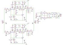
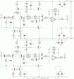
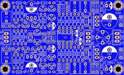
A friend of mine drew the PCB of the mm turntable preamp in the attached diagram but it doesn't work. I have checked our schematic with the original schematic many times. I am waiting for your help.
A friend of mine drew the PCB of the mm turntable preamp in the attached diagram but it doesn't work. I have checked our schematic with the original schematic many times. I am waiting for your help.
Attachments
You didn’t state in what way the unit doesn’t work. However, if you don’t see any errors in your schematic, then it’s time to physically troubleshoot the unit. Basically, begin with the power supply rails by verifying that they are correct. After that, apply a signal to the inputs of the unit (utilize the output of a turntable playing an LP if you don’t possess a signal generator), and follow the signal through the unit with an oscilloscope until it disappears, thereby indicating the malfunctioning section.

Thank you for the information. I do not have an oscilloscope. I made the measurements, there is no problem in the power supply part. the sound is very little but bad.
If both channels are bad, but the supply measures ok, look for miswired ICs.
Remember that the IC pinout is clockwise, as viewed from the bottom (like with tubes).
Also verify the transistor pinouts from their data sheets.
Remember that the IC pinout is clockwise, as viewed from the bottom (like with tubes).
Also verify the transistor pinouts from their data sheets.
Are the corner mounting bolts shorting to the circuit traces or pads, on the top or bottom?
The transistor pinouts can differ from the way the board is designed. They are not all the same.
Just because the transistor package fits the board, does not mean that the pins are in the right holes.
One must verify that everything is correct, and that the parts correspond to the schematic and board.
Since the schematic and the board made from it have never actually worked before,
there can be errors on the board, or wrong pinouts, especially if both channels are bad.
This is not unusual for a DIY project, or even for an engineering prototype in the lab.
Verify each power supply DC voltage at each IC pin and transistor.
there can be errors on the board, or wrong pinouts, especially if both channels are bad.
This is not unusual for a DIY project, or even for an engineering prototype in the lab.
Verify each power supply DC voltage at each IC pin and transistor.
If simply looking for the presence/absence of the test signal, you can still trace that with only a voltmeter. Probe the signal path in A.C. millivolts, from input to output while playing an LP, just as you would with an oscilloscope. The display reading will not be stable because the ‘test’ signal isn’t stable, but that doesn’t matter, only whether the signal is present or absent matters. Where in the signal path the meter reads zero is the circuit location to focus attention. After first verifying the supply rails are correct with the voltmeter, of course.Thank you for the information. I do not have an oscilloscope. I made the measurements, there is no problem in the power supply part. the sound is very little but bad.
- Home
- Source & Line
- Analog Line Level
- MM Phono preamp issue