Hi, what could the problem be with this circuit?

The previous stage has output coupling capacitor.
When I insert the mixer, the volume gets really low.
The mix pot in mid position should be ~unity gain, not atenuation.
I am looking for assembly errors at the physical pcb and cannot find anything by now 🙁.
The previous stage has output coupling capacitor.
When I insert the mixer, the volume gets really low.
The mix pot in mid position should be ~unity gain, not atenuation.
I am looking for assembly errors at the physical pcb and cannot find anything by now 🙁.
There is also a noise, when I turn the pot towards the 'return' end:
- I guess, (B.C1) discharges through the pot and makes noise, since one of the inputs (B.R7) is before the pot wiper to ground.
- I guess, (B.C1) discharges through the pot and makes noise, since one of the inputs (B.R7) is before the pot wiper to ground.
Added a cap just before the +input of UM1A, but the dc problem persists (also the noise when turning the pot to one end).
Have to recall all the stuff about op-amps, cant find the problem now 🙂
Have to recall all the stuff about op-amps, cant find the problem now 🙂
Pot is ok, op-amp is ok, swapped it with another one from a working circuit, checked connection from chip legs to the bottom of pcb..
I picked that circuit idea long time ago and made a pcb that I am assembling now.
It completely turns off one of the sources and maintains output level (at least on simulator).
Now searched the net and I see only inverting version of the circuit.
As I remember I redrew it to be non-inverting but not sure if it is ok (DC bias of the input or whatever)
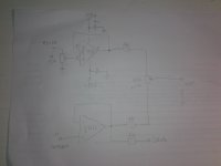
I guess it is this one:


The the +input was DC coupled to ground through the pot/ res network, then I decoupled it (fig. 3), but there is no path for the input DC current to flow (fig. 4).
Checking if it works tomorrow...
The the +input was DC coupled to ground through the pot/ res network, then I decoupled it (fig. 3), but there is no path for the input DC current to flow (fig. 4).
Checking if it works tomorrow...
At the first, pins of UM1A are the same of UM2A...they should be differents?( TL072 is double op amp). Then...schematic is no so clear..what is exactly you need?A mixer? what is before and what is after ( Z , C coupled, etc ) If so, 2 channels? DC or AC coupled ? Why that pot in 'balance' configuration? Regards Ros
It is NE5534 op-amp.
Pot blends two sources (send-return fx loop) and shuts off a source completely at end positions.
Send and return are not connected at all (seporate board with 6.3'' plugs), they have AC coupled op-amp buffers.
Previous and next modules are AC coupled and are working correctly without the mix circuit.

Reworked it, but now it oscilates at a very low frequency....}
It should have gain ~1 at mid to opposite end position and attenuate to shuttoff at the oposite direction.
Pot blends two sources (send-return fx loop) and shuts off a source completely at end positions.
Send and return are not connected at all (seporate board with 6.3'' plugs), they have AC coupled op-amp buffers.
Previous and next modules are AC coupled and are working correctly without the mix circuit.
Reworked it, but now it oscilates at a very low frequency....}
It should have gain ~1 at mid to opposite end position and attenuate to shuttoff at the oposite direction.
Last edited:
The NE5534 is not stable at unity gain without 22pF external compensation cap, so if you are using it in position U2A it will need >= 22pF between pins 5 and 8.
The motorboating is mysterious unless its a side-effect of high-frequency oscillation causing thermal changes that quench the oscillation (squegging).
The motorboating is mysterious unless its a side-effect of high-frequency oscillation causing thermal changes that quench the oscillation (squegging).
Motorboating was probably cause of a loosely soldered element.
Reworked it non-inverting

Now it is dead quiet, no sound at all 🙁 🙁
I removed the module and bypassed it, preamp->poweramp works ok.
Reworked it non-inverting
Now it is dead quiet, no sound at all 🙁 🙁
I removed the module and bypassed it, preamp->poweramp works ok.
This is it, can't believe how stupid...

Maybe it could work in non-inverting setting, but I really don't care now 😡
Maybe it could work in non-inverting setting, but I really don't care now 😡
Last edited:

in fact it seems like there are some short circuits. Give it a tap with the cutter. Remember to place the bypass capacitors very close to the power pins: sorry but I continue no understand the Send pin...Anyway...Regarding the C =22pF suggested to put on the feedback, try to understand with the help of a scope what frequency you have the oscillation on because with R=100ohm you limit the band to 72MHz. In your place I would try to do something like this. since you are sure that the stage before and after are already decoupled with a capacitor. I also expect the next stage to have a Zin ≥10k
Attachments
There is no oscillation, works now.
I will set smth up to look at the signal through PC based scope when I finish the whole thing.
'Send' sends the signal through a parallel external effects chain ('out' on the front panel), then 'return' is mixed with the original signal (same as 'send').
The pot blends both signals as u wish
(How much the effect changes the output signal).
At end positions one of the signals is shut off completely.
I thought send was an output sorry....if it is another input to mix with return input, in theory be better connected it by another op amp to ( same follower configuration gain=1 so to decouple) the extreme of pot ( by a 1k resistor too)..hope the explain is clear. Un saluto Ros
Send - Return 'Buffers' are on another board, where the 6.3'' out-in jacks are.
It decreases gain/2 (external fx may be 9v unipolar supply), phase switch (external fx may reverse the phase) and then recover gain x2 at the return input.
Actually I haven't tested these yet and pray God it works and won't spent ANY more time on this
It decreases gain/2 (external fx may be 9v unipolar supply), phase switch (external fx may reverse the phase) and then recover gain x2 at the return input.
Actually I haven't tested these yet and pray God it works and won't spent ANY more time on this
- Home
- Source & Line
- Analog Line Level
- Mixer circuit problem