Im modeling the crossover for my elsinores in LTSpice, and wanted to try to model the actual speakers as closely as possible.
Following an article at How to Simulate Speaker with Equivalent RLC Circuit the speaker used in the example has two specifications,
Le or Le1k which im guessing is impedance with a 1k signal
and
Le10k, again, im guessing impedance with a 10k signal...
The spec sheet for my speakers SB Acoustics 6” SB17MFC35-8 only has the 1k specification.
Putting the 1k value into a spread sheet im working on is giving me wonky results...
Does anyone know what the 10K value would be for these speakers or have a way to determine it ?
Attachments
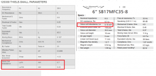
Le would be the voice coil inductance, rather than the impedance. If there is no value at 10k, why not start with the same value?
I'm missing the point in what you want to achieve. If I read correctly LTSpice will only model the impedance of the speaker, but for a crossover simulation you need impedance and frequency response.Im modeling the crossover for my elsinores in LTSpice, and wanted to try to model the actual speakers as closely as possible.
Anyway, since the impedance is published, you can always try different values for Le10k until you get an impedance close to the published one.
Ralf
Allen,Le would be the voice coil inductance, rather than the impedance. If there is no value at 10k, why not start with the same value?
If I said I meant to say inductance, I might be lying lol... But thank you for straightening me out..
If the purpose of this is to create a model that behaves as a speaker does, than Id like to model it as per the articles suggested method...
If you see the article, the actual impedance plot of the virtual built up speaker is close to its real life results...
I could be wrong (have been a few times) but once I have an approximation of how the speaker behaves, and adding the published crossover to them, I might be able to learn more about how my interpretation of Joe's crossover might be affecting anything. Also, I could do the bolster mod 1 and see if I can understand what it does....
Anyway, Le10k is about 60% of Le1K in that model, I may look at other speakers to see whats a typical range and use that for now....
As Ralf says, you can adjust it for best fit. It's a straightforward model and the result should be within reasonable limits.
Whether you're trying to simulate the crossover (one inductor) or the outer impedance compensation, there are extra steps you'll want to follow.
Whether you're trying to simulate the crossover (one inductor) or the outer impedance compensation, there are extra steps you'll want to follow.
As Ralf says, you can adjust it for best fit. It's a straightforward model and the result should be within reasonable limits.
Whether you're trying to simulate the crossover (one inductor) or the outer impedance compensation, there are extra steps you'll want to follow.
Entire day learning more about LTSpice, or that a ground which rotated sideways is not a ground!
Have a ways to go, but something resembling an impedance graph was shown.. Once I figure out a few other anomaly's I will follow Ralfs advice...
Hello AudioFanMan ,
XSim free crossover designer
The "Elsinore Project" Thread - Page 128 - diyAudio
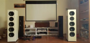
Below my speakers inspiration from Elsinore, Peerless 830875 + Fountek JP3.0 in 2.5 way.

BR
Pascal
A tool like Xsim would be more adequate IMHO :Im modeling the crossover for my elsinores
XSim free crossover designer
As I recall bolster mod was concerning Elsinore mk4/5 using Peerless 830875 😕Also, I could do the bolster mod 1 and see if I can understand what it does....
The "Elsinore Project" Thread - Page 128 - diyAudio
Below my speakers inspiration from Elsinore, Peerless 830875 + Fountek JP3.0 in 2.5 way.
BR
Pascal
Attachments
Last edited:
- Home
- Loudspeakers
- Multi-Way
- Missing Le10k specification 6” SB17MFC35-8