All,
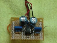
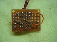
Pictures and schematic of my mint tin phono amplifier. Circuit is a simplified Vinyl Addicts (Thorsten Loesch) El Cheapo phono stage with a TLE2426 rail splitter power supply section to enable operation from a single 9V battery. Because the amp is a prototype, I tried to balance cost verse performance so, opamp is a AD823, resistors are standard 5% carbon film, filter caps are high quality polypropylene and coupling caps are small 50v Nichion electrolytic cross over caps. Amp is dead quiet and for such a simple/compact circuit, I was absolutely amazed at how good it sounds
Cheers -ALBQ
An externally hosted image should be here but it was not working when we last tested it.
An externally hosted image should be here but it was not working when we last tested it.
An externally hosted image should be here but it was not working when we last tested it.
Hi
Looks good. How do you get the rails up to +/- 8 V using a TLE2426 and a single 9V since TLE output is 1/2 Vin. Have you compared the sound to using just 2x9v batteries? (i.e. what is the sonic impact of the TLE2426 part).
Looks good. How do you get the rails up to +/- 8 V using a TLE2426 and a single 9V since TLE output is 1/2 Vin. Have you compared the sound to using just 2x9v batteries? (i.e. what is the sonic impact of the TLE2426 part).
Supply rail
Infinia,
Sorry about that, Eagle CAD schematic still showing 9V. Originally sized PCB to fit two batteries in the tin but, would not work with RCA plugs. I have not tried a higher supply voltage although pretty happy with how it sounds at +/- 4.5.
Cheers -ALBQ
Infinia,
Sorry about that, Eagle CAD schematic still showing 9V. Originally sized PCB to fit two batteries in the tin but, would not work with RCA plugs. I have not tried a higher supply voltage although pretty happy with how it sounds at +/- 4.5.
Cheers -ALBQ
have you tried the opa2228, i had much better experiences with the 2228 at low voltages.. it seems the 2134 sounds flat and un happening at 4.5v...🙂
Op Amps
hacknet,
I have tried the AD823, OPA2132 and OPA2227. Of the three, the AD823 is the most detailed but, can be a bit abrasive on certain material, the OPA2132 is detailed and warm but, somewhat muffled and the OPA2227 is the somewhere in between. 9/10's the detail of the Analog Devices while retaining most of the warmth of the Burr-Brown (Ti) op amps. OPA2227 is a untiy gain stable version of the OPA2228/OPA2227 series.
Cheers -ALBQ 😎
Seems like you could fit 2 batteries in there if you eliminated DC block electros. Moved the power switch to same side of RCA's and scooched PCB just underside of RCA center pins. Looks tempting to build.
I wonder if anybody has tried a LT1057 dual Op-amp in a RIAA amp like that? It's little pricey at 9 duckets a pop though.
I wonder if anybody has tried a LT1057 dual Op-amp in a RIAA amp like that? It's little pricey at 9 duckets a pop though.
Mint Tin Phono
Infinia,
I designed the PCB so that it would fit in the tin with two batteries so, I am sure that if I arranged the power switch and RCA's, should fit without a problem. Also, one of the reasons I used this circuit is it is easy to roll opamps. Can change the sound quite a bit with different opamps and any 8 pin dual opamp will fit so, many choices.
Cheers -ALBQ
Mint Tin Phon EagleCAD PCB File
All,
In case you would like to build one, EagleCAD PCB Board file for Mint Tin Phono Amplifier.
Cheers -ALBQ
http://mywebpages.comcast.net/gillespie147/Junk/MintTinPhono-EagleCAD.brd😉
All,
In case you would like to build one, EagleCAD PCB Board file for Mint Tin Phono Amplifier.
Cheers -ALBQ
An externally hosted image should be here but it was not working when we last tested it.
http://mywebpages.comcast.net/gillespie147/Junk/MintTinPhono-EagleCAD.brd😉
Mint Tin Phono Battery Life
graeme uk,
Not sure how long the battery will last but, have been using it for at least a dozen plus hours and no sign of stopping. The basic circuit setup - opamp, feedback with rail splitter is similar enough to an opamp based headphone amp, with the exception of RIAA, that would expect that battery life is pretty good. I have made several CMoy type headphone amplifiers and battery life is typically not a problem.
Cheers -ALBQ
Okay, I have "assembled a total of 3 units, troubleshooting each, resoldering, dismantling, etc. The best I have now is low volume in one channel (right) and dead left channel. Ordinarily, I would keep going. But, this is way too hard for a neophyte like me. The fun is fast departing. Any ideas? I used the Tangent tutorial to the letter

Mint Tin Phono
Bob,
Couple of questions 1) are you using the original schematic? 2) could you post a picture of your build? I have built a couple of these now and all work fine. If you could provide a picture or two and some infomration, I will try to help.
Thank you -ALBQ
Bob,
Couple of questions 1) are you using the original schematic? 2) could you post a picture of your build? I have built a couple of these now and all work fine. If you could provide a picture or two and some infomration, I will try to help.
Thank you -ALBQ
Mint Tin Phono
Bob,
Hmmm... Hard to tell whats going on from the pic. At a glance, generally looks like I would suspect - very similar to a CMoy headphone amp layout. Do you have a voltmeter? The first thing to check are the +/- rails on the opamp - should read +/-4.5V from virtual ground. Let me know if this is correct and will move to the next step.
Thank you -ALBQ
Mint Tin Phono
Bob,
If you measure -4.5V (PIN4) and +4.5V (PIN8), would ask what IC you are using? All of the Burr Brown / Anolog Devices dual opamps are the same pin out so, if the rails are corrct, would need to be something else wrong. Most likely in the feeback loop. What are the voltages at each pin of the opamp?
Thank you -ALBQ
I'm using BB/TI opamp. I'll have to consult my basic electronics book for measuring pins of the opamp, unless it just requires a positive reading per leg against a common negative. I just rechecked my test pins and now I can hear the source very faintly in BOTH channels! When I unplug the 9 volt, no change on the audible output. It's as if the amp is doing nothing but allowing a "pass through" signal with no amplification.
- Status
- Not open for further replies.
- Home
- Source & Line
- Analog Line Level
- Mint Tin Phono Amplifier