I'm back into tinkering with tubes again now that the cold weather is here.
I found this schematic online and had a question about the output stage. It lacks a dedicated phase inverter and I don't see why this method of phase inversion was chosen over the option shown in the second image. Can someone explain? Any advantage to the design in the second photo?


I found this schematic online and had a question about the output stage. It lacks a dedicated phase inverter and I don't see why this method of phase inversion was chosen over the option shown in the second image. Can someone explain? Any advantage to the design in the second photo?
Attachments
I found this schematic online and had a question about the output stage. It lacks a dedicated phase inverter and I don't see why this method of phase inversion was chosen over the option shown in the second image. Can someone explain?
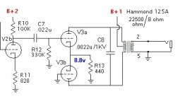
That first design is a self splitting LTP/PA in one. This particular implementation is horrible. A 440R resistor isn't nearly enough tail load, and a CCS would be a helluvalot better (though it'll require a negative rail). It also enforces Class A operation, since the limit of plate current swing will be between 0mA and Itail.
Any advantage to the design in the second photo?
It will probably perform better than a cathodyne if your DC rail voltage is limited. (In that case, you could always substitute a MOSFET for a triode and use that for your cathodyne (sourceodyne?) splitter instead.
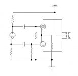
The phase splitter (first triode) in the first schematic has zero gain. The gain stage in the second schematic has a good deal of gain but the output tubes have less gain since they operate as an LTP with a shorter than usual tail. There are trade offs in both cases and the self split version (second schematic) will have a somewhat lower total power output and imperfect balance. This will cause it to sound somewhat like an SE amp, but allow the use of a P-P OPT.
I explored many versions of this circuit and settled on something quite like this for the 2 watt guitar amp in the Hundred Buck Amp Challenge thread. The schematic is in post # 1021.
http://www.diyaudio.com/forums/instruments-amps/190738-hundred-buck-amp-challenge.html
I now have a version using a mosfet phase splitter that can be disabled allowing the 2 watt "quasi SE sound" and 5 watts of full P-P pentode terror.
It will probably perform better than a cathodyne if your DC rail voltage is limited. (In that case, you could always substitute a MOSFET for a triode and use that for your cathodyne (sourceodyne?) splitter instead.
I thought the 2nd pic IS a cathodyne PI.
The phase splitter (first triode) in the first schematic has zero gain.
The first tube in the first drawing isnt a phase splitter. It's just a gain stage. Shouldn't a plate follower have some gain?
The second stage doesn't have a gain stage. It's just a cathodyne phase inverter (from what I understand).
I'm wondering why that designer chose to build the output stages the way he did. My thought was he could have made better use of that first triode as a PI. If he required it for gain, he would have been better off paralleling the triodes of V3 and wiring it for SE to keep his first triode gain stage.
Last edited:
The "Compact Amp" with the self splitting output tubes was published in Electronics World, June 1961: Compact Hi-Fi Power Amplifier by Melvin Leibowitz
As pointed out above, it is not a great concept. It has been elaborated in a number of steps published at: Simple EL84 poweramp/integrated
SB.
As pointed out above, it is not a great concept. It has been elaborated in a number of steps published at: Simple EL84 poweramp/integrated
SB.
The first tube in the first drawing isnt a phase splitter. It's just a gain stage. Shouldn't a plate follower have some gain?
You are right. The schematics arent visible while posting a reply and my brain goes fuzzy at 11PM, that's why I turn the bench power off at 10PM to avoid shocking moments. I got the schematics reversed in my post of last night.
The bottom schematic is a conventional design and the first stage phase splitter has no gain. The unbypassed cathodes in the output stages will cause a mild gain drop as long as the tubes remain in class A and a rather serious gain drop if driven into AB teritory. The output impedance increases in both cases. Add a cap if you need more gain.
The top schematic is a self split output stage that acts as a rather imperfect LTP. The input stage does indeed have gain. The major advantage here is a low parts count, since it doesn't do anything real well. It does allow the use of an ungapped P-P OPT in a circuit that provides a somewhat SE like sound. I am exploiting this property in a guitar amp that has $40 in total parts count. The extra output tube costs $1. The difference between a SE and a P-P OPT is $7. The design works but I can't get the THD below 2% at any power level and it rises with power output. It's good for a guitar amp, but I wouldn't try it for HiFi.
I'm back into tinkering with tubes again now that the cold weather is here.
I found this schematic online and had a question about the output stage. It lacks a dedicated phase inverter and I don't see why this method of phase inversion was chosen over the option shown in the second image. Can someone explain?
Because it's a guitar amp. Not a hifi amp.
The whole point of this amp was to get very low output volume (power), and lots of gain. A 'proper' PI would sacrifice gain but result in more output volume than necessary, the exact opposite of the design intention.
Here's the full schem for the benefit of everyone. Notice how it's totally anti-fidelity...?
An externally hosted image should be here but it was not working when we last tested it.
Last edited:
Why not build a SE amp?
Your schematic will not give true push-pull operation. There will be much more 'push' than 'pull' which will severely limit the available output power (and increase the distortion).
Since you don't require a whole lot of power, it would seem that a SE design might be a better and less costly solution.
A 'better' solution is meaningless here, since this is a musical application, not a hifi one. And as for more costly, PP transformers are smaller and cheaper, generally, than SE (maybe not if you live in the indulgent US, but when sharing a project with the whole world you can't take it for granted that everyone has a box full of Hammonds...) Maybe Doug had one already, and needed to put it to good use. I suppose one could argue that the distortion signature of a push-pull amp is slightly more favourable than SE for guitar purposes, but I suspect Doug Hammond's main reason for doing it was "what if". SE has been done, it's boring. But an ECC83 cascode and ECC82 self-split output stage? That's not something you see every day.Why not build a SE amp?
Your schematic will not give true push-pull operation. There will be much more 'push' than 'pull' which will severely limit the available output power (and increase the distortion).
Since you don't require a whole lot of power, it would seem that a SE design might be a better and less costly solution.
Last edited:
The whole point of this amp was to get very low output volume (power), and lots of gain.
For several good discussions and about as many different opinions, read through the Hundred Buck Amp Challenge thread. The whole point is to make a low volume practice amp that can go from clean to full metal racket at a practice amp (or recording studio) volume level. The maximum parts cost for this challenge must be under $100.
Several builders did indeed propose SE designs. A true SE OPT starts at about $15 and can easilly hit $30 for a 2 watt amp. Using the self split output stage still runs nearly equal DC currents through both sides of the OPT so that transformers not intended for OPT use can be repurposed as an OPT with good results.
My small amp discussed above uses a 70 volt distribution transformer that costs $6 and sounds quite nice. I have a larger design that cranks out 15 watts using a pair of '84s for output through a $12 power supply toroid. It has a variable attenuator to adjust the output from zero to 15 watts. It also uses a more traditional circuit with 4 triode gain stages before the LTP PI for a full metal racket sound if desired.
Dug up a quote from Doug Hammond:
"Every year or so somebody wants to "improve" the Firefly. People have suggested "adding a PI to a Firefly and running it class A/B" and so forth. That's fine, but in my mind it's no longer a "Firefly" at that point. The Firefly is inefficient, brute-force, and in some ways a slapped-together design- but it is what it is."
"Every year or so somebody wants to "improve" the Firefly. People have suggested "adding a PI to a Firefly and running it class A/B" and so forth. That's fine, but in my mind it's no longer a "Firefly" at that point. The Firefly is inefficient, brute-force, and in some ways a slapped-together design- but it is what it is."
but when sharing a project with the whole world you can't take it for granted that everyone has a box full of Hammonds
Hammonds are not a US product and while a decent product, it is not one that an overindulgent person, wherever they live would have a box full of.
In todays economy I don't see how you can single out any one country as indulgent. It may seem that way to the rest of the world because of the Hollywood lifestyle shown in the media, but most of us are not over indulgent.
I sell tube amplifier boards all over the world. I often get pictures of the finished amps. The majority of them are built well with good parts. A small fraction are however "over the top" projects where the builder spends more on the chassis / cabinet than I spent on my entire system. Most of these were NOT US builds.
When sharing a design with the whole world one must look at the parts available to the whole world. Tubes like the multi section compactrons are not available outside the US. The selection of OPT's available in the US, Europe, and Asia are all different. The selection of all transformers is even more limited in Australia and Africa. Things like 100 volt line matching transformers are not available in the US. It is therefore wise to look at what is available world wide and chose from that list of parts.
Dug up a quote from Doug Hammond:
I have never built the Firefly. I tried the self split output stage in my super low buck design and it does work. It works well for what it is and I haven't found much else to generate the same sound for less money. As Merlin and I pointed out, it is a guitar amp and probably would not be suitable for HiFi, but I have seen some HiFi schematics with self split output stages.
Yes, I know Hammond's are Canadian, but they are representative of the huge range of parts available to the US; a lot of US posters seem to think the rest of the world has it just as good.In todays economy I don't see how you can single out any one country as indulgent. It may seem that way to the rest of the world because of the Hollywood lifestyle shown in the media, but most of us are not over indulgent.
OK I was being a little tongue-in-cheek, but Hollywood lifestyle has nothing to do with it. Just compare the price of a BigMac, petrol, clothes, a set of screwdrivers... with those in any other country. The rate at which the US consumes 'stuff' is genuinely frightening to the rest of us. The standard of living in the US is exceptionally high. Of course, this goes together with the longest working hours and some of the most extreme poverty in the developed world, but I'm getting OT now!
but they are representative of the huge range of parts available to the US
Yes, we do have a lot of parts to choose from, but most of it is made elsewhere. For affordable OPT's we have Edcor. For the better stuff there is Electra Print and a few low volume suppliers. Other than that quite a few "indulgent" builders seem to be sourcing from the UK, Europe or Asia. The caps and resistors all come from China except for the ultra high end stuff. I don't know where it comes from since I stick to the Chinese stuff.
As for the standard of living in the US, it isn't what it used to be. Yes the prices of a lot of stuff is lower than in other places and the rate of consumption of stuff has been fueled by the stupid idea that you can spend more money than you make forever. Well, the credit cards are maxed, and the limit has been reached.......oh wait the idiots have raised the limit again.......
Back to the regular scheduled program, no matter where you get your parts, a properly made SE OPT will be bigger and more expensive than a P-P OPT of the same power range. The SE OPT should have a gapped core to keep it from saturating due to the unbalanced DC current flowing through the primary.
Some of the builders in the HBAC claim to be using a power (mains) transformer as an SE OPT. My experience has not been good with doing this, but I haven't tried it for a guitar amp. The simple self split circuit shown affords a somewhat SE type sound with a garden variety power transformer as an OPT. Of course you could use a Hammond or other dedicated P-P OPT, but that is more costly than necessary for a low powered guitar amp.
I have tried the self split circuit with high Gm pentodes and the balance is still not good enough for HiFi unless you put a CCS in the tail (cathode circuit).
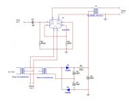
Not to bump an old thread but I did refer back to this a few days ago and built a self-split PP headphone amp with a pair of 6SN7s and some "too small for speakers" OPTs.
It sounds rather nice. Might be an easy starter project for someone. It's built with two 12v CT transformers.
Schematic.

It sounds rather nice. Might be an easy starter project for someone. It's built with two 12v CT transformers.
Schematic.
Attachments
Last edited:
- Status
- Not open for further replies.
- Home
- Amplifiers
- Tubes / Valves
- Mini amp questions