do we need a miller cap on LME 49810 based designs ?
Can someone point out to me the miller cap on Rod Elliotts P3A, I think it's C6 but then shouldn't there be a simmilar one on the other side also ?
Can someone point out to me the miller cap on Rod Elliotts P3A, I think it's C6 but then shouldn't there be a simmilar one on the other side also ?
An externally hosted image should be here but it was not working when we last tested it.
do we need a miller cap on LME 49810 based designs ?
Can someone point out to me the miller cap on Rod Elliotts P3A, I think it's C6 but then shouldn't there be a simmilar one on the other side also ?
An externally hosted image should be here but it was not working when we last tested it.
Dear,
In the LME49810 the cap between the biasM and Comp pin is the Miller cap. There is an additional circuit with with 3.3K and 75pF from comp to ground which I really recommended for the LME49810 as well (it was intended for the LME49811).
With kind regards,
Bas
Dear,
In the LME49810 the cap between the biasM and Comp pin is the Miller cap. There is an additional circuit with with 3.3K and 75pF from comp to ground which I really recommended for the LME49810 as well (it was intended for the LME49811).
With kind regards,
Bas
Is this there in the datasheet for LME 49811 or an appnote ?
Yes, C6 is a Miller cap. There does not need to be another one.
I couldn't help it C4 looks very simmilar in usage ..but it's placed one stage behind ?
Is this there in the datasheet for LME 49811 or an appnote ?
See here 😉
With kind regards,
Bas
Attachments
See here 😉
With kind regards,
Bas
thanks a lot, I have incorporated these in my design now..I too remember about someone from national on the forum suggesting these changes
Exactly. It is also a Miller cap and it is for another stage.
please bear with me... If you look at rod elliott's design he has a miller cap from the output stage to the driver stage and another in the VAS( I guess C4 is in VAS right ? ). LME has only one in the Vas stage, have they left the other one i.e. in the output to driver stage upto the designer ?
Yes, they left it to the designer, because they cannot know what output stage he chooses and if it needs a Miller cap or not.
C4 is the usual VAS Miller capacitor you see in designs. C6 is a Miller cap due to the CFP output stage, needed to prevent oscillation in this stage. If it was a regular EF output stage, C6 would not be present.
C4 is the usual VAS Miller capacitor you see in designs. C6 is a Miller cap due to the CFP output stage, needed to prevent oscillation in this stage. If it was a regular EF output stage, C6 would not be present.
hmmm...then I would definitely need that
guy's please give your thoughts on this , I had posted this some time back but project was shelved for some time . I am really gonna make some pcb's if the basic design seems okay..tweaking the values afterwards is fine.
The output BJT's are actually MJL 1302 and 3281, Eagle had only TIP so used that in schematic.
The output BJT's are actually MJL 1302 and 3281, Eagle had only TIP so used that in schematic.
Attachments
Last edited:
With EAGLE you are going to want to learn to make your own devices pretty quick. I decided to make my own transistor lib - EAGLE does actually have all the package layouts needed, including TO-247 and TO-264 devices. Using TO-247 is ok but remember that TO-264 is wider.
With EAGLE you are going to want to learn to make your own devices pretty quick. I decided to make my own transistor lib - EAGLE does actually have all the package layouts needed, including TO-247 and TO-264 devices. Using TO-247 is ok but remember that TO-264 is wider.
I usually take no-scaling prints from PDF and check out the parts fit, if something doesn't fit change. I'll check this out whether the transistors actually fit.
guy's please give your thoughts on this , I had posted this some time back but project was shelved for some time . I am really gonna make some pcb's if the basic design seems okay..tweaking the values afterwards is fine.
The output BJT's are actually MJL 1302 and 3281, Eagle had only TIP so used that in schematic.
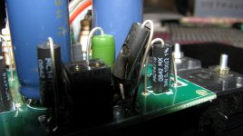
finally got around to making some pcb's and testing this amp, amp runs fine and plays nicely for around a minute or so before blowing up 0.1ohm resistors in the output R5 and R4. If you put a new resistor in it will do the same thing in another minute or so..rest of the amp seems fine nothings overheating smoking and sounds good also.
I had simulated this extensively on multisim and found the voltage drop across it to be only around 0.3 volts even with 6A current from the amp..I would really appreceate some help on this..
Attachments
Last edited:
 Questions from the peanut gallery. 1) 6 Amps should be .6 volts across the resistor. Either way, power is either 1.8W or 3.6 watts. So what wattage and type resistor? The current limit circuit limits the current to about 6 amps any way. Which of Ohms laws are you violating? Maybe unrelated, but what idle current are you setting it to. 6 Amps will be quite loud if its signal as opposed to bias current. Good luck with it.
6 amps was just in a simulation. I had not measured the acutal current output when I was running it and total output from both the halves, so each half was delivering only half the total current.. so it should be around 0.3 volts across each resistor. The resistors were 3W wirewound types, I agree this is a bit undersized for the app but to reach 3W dissipation level I would need much more than 3 amps.
Am I just seeing the effects of thermal runway ?..My Vbe multiplier was not coupled to the heatsink where my output transistor was mounted.It was coupled to the driver transistor, which itself has separate smaller heatsinks . I have now moved the Vbe multiplier to the main heatsinks where the output transistors are mounted. Should I move my driver transistors also ? Should the temperature compensating element alone mounted on the main heatsink suffiice ?
turned out that CFP's are sensitive to driver temperature rather than output transistors (I didn't do enough research the first time) and also MJE340 as a Vbe multiplier is too slow, I need a faster reacting one like a BD139 ? ..I tried these changes sometime back, the amp runs for slightly longer durations now, around 10-15 mins then the bias current goes through the roof. Is there anything better that I can use instead of a BD139 as a Vbe multiplier. I have attached the BD139 directly on top of my driver transistors.
BTW I could easily make up an EF type but don't want to let go CFP without making it work 😀
BTW I could easily make up an EF type but don't want to let go CFP without making it work 😀
- Status
- Not open for further replies.
- Home
- Amplifiers
- Chip Amps
- miller cap