Hi!
This is my first post here. I've been reading the forums quite a lot, and I have a question for which I have found no answer via search.
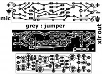
I'm making a pcb for a small electret mic preamp. It's a really small pcb, the circuit generates a balanced signal from an electret capsule. It is phantom powered. I'm a complete newbie at making pcbs by the way.
I know about ground planes that can create ground loops, and I know about star-grounding too.
My question : On a given pcb, in this case mine, is it better to fill most of the empty area with ground traces, as long as no ground loops are generated? Is this a good pcb design practice?
Here's my original pcb, followed by it's star-ground-plane version.
Thanks a lot!!
Georges
This is my first post here. I've been reading the forums quite a lot, and I have a question for which I have found no answer via search.
I'm making a pcb for a small electret mic preamp. It's a really small pcb, the circuit generates a balanced signal from an electret capsule. It is phantom powered. I'm a complete newbie at making pcbs by the way.
I know about ground planes that can create ground loops, and I know about star-grounding too.
My question : On a given pcb, in this case mine, is it better to fill most of the empty area with ground traces, as long as no ground loops are generated? Is this a good pcb design practice?
Here's my original pcb, followed by it's star-ground-plane version.
Thanks a lot!!
Georges
Attachments
In low level circuits as mic pre amplifier,
it is good with a groundplane area around the input.
When such is around the tracks of input,
it acts in a way like the shield around a signal wire.
Sometimes you can also have to put a little auminium box or screen
as a shield around the input = first transistor.
it is good with a groundplane area around the input.
When such is around the tracks of input,
it acts in a way like the shield around a signal wire.
Sometimes you can also have to put a little auminium box or screen
as a shield around the input = first transistor.
Thanks for the reply!
But as in the photo I attached, is it good practice to put ground planes everywhere where there's nothing (as long as there's no loop) ?
Save on etchant too!
But as in the photo I attached, is it good practice to put ground planes everywhere where there's nothing (as long as there's no loop) ?
Save on etchant too!
Save on etchant too!
This would be the primary reason for filling up with copper (it's done for this reason in the professonal domain too).
As for RF shielding, keeping one side predominantly copper leaves only half the job done if you don't also include a box-type shield on the component side. But I don't think that this is essential for your application. Just ensure that you have some form of bandwidth limiting (low-pass filter) at the input of your circuit, though.
- Status
- Not open for further replies.