Hi
I have a Musical Fidelity B200 that has 4 X 1,5K bleeding resistors from +- rail to ground.
The question is why?
Why 4 bleeding resistors that dissipate about 2,4 W each, and allocated near voltage regulators! Each one is soldered less than half an inch from a TIP31/32 regulator transistor that gets .
.
I changed their value to 2,2K in order to lower the heat. The sound doesn’t seem to change.
Anybody knows something about this? What are these bleeding resistors for (I mean the low resistor value)? And, can I change it´s value? But then, why has the designer used such low values?
Thanks
I have a Musical Fidelity B200 that has 4 X 1,5K bleeding resistors from +- rail to ground.
The question is why?
Why 4 bleeding resistors that dissipate about 2,4 W each, and allocated near voltage regulators! Each one is soldered less than half an inch from a TIP31/32 regulator transistor that gets
.I changed their value to 2,2K in order to lower the heat. The sound doesn’t seem to change.
Anybody knows something about this? What are these bleeding resistors for (I mean the low resistor value)? And, can I change it´s value? But then, why has the designer used such low values?
Thanks
If that's all they are doing (bleeding off the cap charge), then there should be no problem increasing their size to reduce heat.
If the resistors are bleeding off charge after a series regulator, they may be there to ensure the capacitors after the regulator discharge faster than the capacitors before the regulator on shutdown, to avoid a reverse bias condition across the regulator.
Does the regulator have a reverse protection diode?
Does the regulator have a reverse protection diode?
Thanks for your reply
In fact the bleeding resistors are not after the regulators. The regulators are the power supply for the LM318 (+-12V)
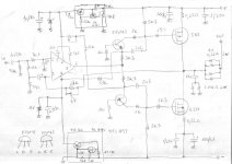
This is the schematic of the amplifier, however the bleeding resistors are not shown and they are from + rail (about 60V) to ground and from – rail (-60V) to ground.
Maybe it has to do with “shutting down” the amp ( to avoid the bump on the speakers when lm318 looses control?). This amplifier has no speaker protection. But I took them off, turn the amp down and up and heard no bump … maybe I’m wrong!
I really would like to understand the reason (behind the waste of 10W in heat) that made the designer take this option. And why 4 resistors that are very near to regulators that gets very hot?
In fact the bleeding resistors are not after the regulators. The regulators are the power supply for the LM318 (+-12V)
This is the schematic of the amplifier, however the bleeding resistors are not shown and they are from + rail (about 60V) to ground and from – rail (-60V) to ground.
Maybe it has to do with “shutting down” the amp ( to avoid the bump on the speakers when lm318 looses control?). This amplifier has no speaker protection. But I took them off, turn the amp down and up and heard no bump … maybe I’m wrong!
I really would like to understand the reason (behind the waste of 10W in heat) that made the designer take this option. And why 4 resistors that are very near to regulators that gets very hot?
Attachments
Hi jmmartins,
There is no shortage of products designed by a team that was not / is not competent. I see this more these days than much earlier in time. The early "plastic years" (1979 ! 1988 about) were also dark times for consumers, although some of the best products were also brought out then.
-Chris
Normal for these models. Just very poor planing and a desire to make the unit appear more class "A" to customers and salespeople. They also do assist in minimizing turn off thumps. They can't control how fast those caps will discharge after some time, and they need the output supply to die faster than the supply for the LM318 (or whatever op amp is in there) does. That entire design is flawed.The pcb was in very bad shape caused by the heat produced by those resistors (it was toasted and with a hole under). The nearby regulators got so hot that the copper tracks under the pcb at which they were soldered got separated from the pcb, and the regulators were loose. The same thing happened to both my B200, exactly the same problem.
There is no shortage of products designed by a team that was not / is not competent. I see this more these days than much earlier in time. The early "plastic years" (1979 ! 1988 about) were also dark times for consumers, although some of the best products were also brought out then.
-Chris
Just had another look at the circuit diagram for the B200 and... yes you are right😱
Could well be there to speed up the discharge of the reservoir caps after switch off as this series of amps can produce a squeal or whistle during power down as the feedback loop loses control.we sometimes added resistors to the PSU's of A370 and P270 (basically a bigger version of the same amp) amps to even up the rate of discharge between the + & - rails when customers returned them complaining of this phenomena.
Could well be there to speed up the discharge of the reservoir caps after switch off as this series of amps can produce a squeal or whistle during power down as the feedback loop loses control.we sometimes added resistors to the PSU's of A370 and P270 (basically a bigger version of the same amp) amps to even up the rate of discharge between the + & - rails when customers returned them complaining of this phenomena.
Maybe 'bleeder' resistors rather than 'bleeding' resistors. It makes you sound like you're very annoyed to find them there at all!
- Status
- Not open for further replies.
- Home
- Amplifiers
- Solid State
- MF B200 bleeding resistors