Hi y'all! In working on a 15kw vttc which is essentially a class E. Normally these use a silicon diode on the input but I wanna go full old fashioned and use a mercury rectifier. I have two 1.25a 10kv 872a that I can use. While I fully understand the danger I don't know the most about electrical characteristics. Mostly I wanna know is how well to they handle overloaded RMS current and if I can put two in parallel? I know they don't like high peak but I think for short periods and reduced lifespan I can over current. If I put two in parrales i am concerned just one will fire and drop the voltage to where the other will not
To employ them in parallel you will need balast resistors. They don't behave well at high current. I would use your silicon diode as normal and use a dropper/balast resistor placing the rectifier valve across the resistor if single phase. The resistor will drop enough voltage for the current to give the desired blue U/V glow without causing too much of an overload.
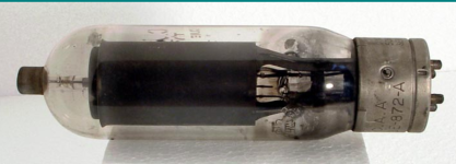
Here is an extract from the valve data sheet if you think it is still suitable.
Here is an extract from the valve data sheet if you think it is still suitable.