no.
FETs are measured differently from BJTs.
Don't try to measure absolute values using our amateurish set up jigs.
It is far better to compare DUT to REF when trying to find matches.
BTW,
that jig uses constant base current rather than constant collector current for measuring hFE. This will give very misleading results.
Many DMM have a similar circuit for their hFE function because it is cheap. It is only good for grouping similar devices. It is absolutely no good for selecting matched pairs.
Last edited:
Erno Borbely shows a JFET measurement jig on his website --
http://www.borbelyaudio.com/adobe/ae599bor.pdf
http://www.borbelyaudio.com/adobe/ae699bor.pdf
http://www.borbelyaudio.com/adobe/ae599bor.pdf
http://www.borbelyaudio.com/adobe/ae699bor.pdf
Erno Borbely shows a JFET measurement jig on his website --
http://www.borbelyaudio.com/adobe/ae599bor.pdf
http://www.borbelyaudio.com/adobe/ae699bor.pdf
The figure 5 jig looks easy enough to build, but how is the jig used?
And if the bjt testing jig I posted not adequate, any suggestions for a better one?
As Andrew pointed out, the setup you posted works for small signal bipolar transistors, not JFETs.
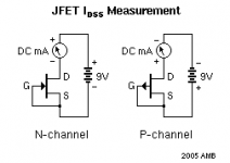
For JFET's it's helpful to know I(dss) and gm. Idss is measured when the switch next to the voltmeter is depressed and the Source of the JFET is grounded.
The pinch-off voltage V(p) is measured by connecting the source to -10V through a 1Meg resistor -- gm can then be calculated
gm =~ 2x Idss / V(p)
Attachments
yes.
To give an enhanced capability, combine the two jigs into one by joining the two sources together. This will automatically join the two gates together and ensure Vgs = 0V.
Replace the mAmmeters with a pair of accurately matched ~100r resistors.
Feed +9V, or if you have it +10.2V to +11.0V, to the two drain resistors.
Measure the voltage drop across the drain resistors and/or compare the voltage between the two drains.
This can be fitted to an 8pin dip socket so each FET can be face to face with it's partner. A spring clip, a bulldog clip (for paper printoffs) is perfect, allows the two FETs to be equal Tc if they are of equal Id. Temperature is the biggest problem for us. We cannot hold Tc at 25degC easily.
- Status
- Not open for further replies.
- Home
- Design & Build
- Equipment & Tools
- Measuring Hfe