OK, so I've built a few kit amps and have got the bug, now I would like to measure their power outputs, just for fun really and to see how the various chips perform compared to their published specs.
I think I have the basic concept: inject signal into front end of amp, feed amp output into appropriate load (8ohm in my case) and measure voltage across said load, do some maths.
However I would like to know some specifics before I start injecting/measuring - don't want to blow anything up, and yes I have searched but couldn't find anything to answer my q's.
So, firstly:
a) my amp has a volume pot - do I crank it fully up then slowly increase the injected sine wave until I see clipping then back off the input for a clean signal, then take the output measurement?
b)or, do I set a known p-p voltage in and then use the amp volume to wind it up to clipping?
c) do I split the sine wave signal to do the 2 channels or just do one channel at a time? i.e. does running an amp with only one input have any detrimental effects on it, also running with only one channel output loaded?
I think I might be trying to make it more complicated than what it actually is but just want to confirm before I start. If anybody has any good links to these procedure I'm keen to read those as well.
Thanks!
Hi Mike, I've got a fluke 87 DMM, a Chinese DSO (hantek 5072P), a Chinese FG085 miniDDS function generator and a couple of those gold 8ohm 100W resistors for a dummy load.
I'll be testing amps in the (supposedly) 20-50W range.
Steve
I'll be testing amps in the (supposedly) 20-50W range.
Steve
DSO is typically 8 bit, maybe one more bit with averaging - good for eyeball debugging, stability gross frequency response
but useless for THD, IMD, fine frequency response
for audio measurements even PC motherboard sound chipsets are better
but many go with "prosumer" soundcards
both need attenuation/filtering/input protection
100 W R usually have to be screwed down to a heatsink to reach the rated power
but useless for THD, IMD, fine frequency response
for audio measurements even PC motherboard sound chipsets are better
but many go with "prosumer" soundcards
both need attenuation/filtering/input protection
100 W R usually have to be screwed down to a heatsink to reach the rated power
Yes, but I only want to measure RMS power output, not THD.
Yes, I have the resistors bolted to a heatsink.
Thanks
Yes, I have the resistors bolted to a heatsink.
Thanks
OK, I'll try to answer your questions.
a) my amp has a volume pot - do I crank it fully up then slowly increase the injected sine wave until I see clipping then back off the input for a clean signal, then take the output measurement?
If testing only for power output into a resistive load that's a valid method, but remember that real world speakers present a load that varies with frequency.
All speaker drivers will have an impedance "hump" around resonant frequency at the lower end of their frequency range, followed by a long gradual dip ending with a rising impedance at the top of their range, and if you are diving a speaker system with multiple drivers and a passive crossover network it gets even more complicated, and because of that, some speakers can present a load that can really strain even the best amplifiers or even cause them to break into oscillation. So a simple resistive test will tell you the maximum output only at that resistance and won't really give you the entire picture.
b)or, do I set a known p-p voltage in and then use the amp volume to wind it up to clipping?
If you use method "a)" it will primarily test only the raw power output of a power amp, regardless of whether or not it's just a power amp, or part of an integrate preamp/power amp or a receiver. Method "b)" can also test the preamp section, if there is one.
c) do I split the sine wave signal to do the 2 channels or just do one channel at a time? i.e. does running an amp with only one input have any detrimental effects on it, also running with only one channel output loaded?
You can do it either way, but doing both (or all) channels at the same time will give total power output with all channels driven, which is generally considered the most valid approach. It's usually OK to leave inputs open, but some prefer to insert a shorted plug to prevent any stray noise getting in, especially if you're in a potentially high RFI environment, like from fluorescent lights for example. As far as leaving amp outputs unloaded, I don't recommend doing that, nothing good can come from it.
Others may want to chime-in here and add to what I've told you, but for simple power output measurement, those are the essential basics. And as always, be safe; be aware of where you put your hands; where your wires are; where your tools go; and be especially careful working around high voltages, be aware of things like hot power resistors, and so on. A little common sense goes a long way for making sure you don't have a bad day.
I recommend check out the Elliott Sound Products site, there's a ton of really good info there, here's the link: http://sound.westhost.com/index.html
Mike
Last edited:
Awesome - thanks Mike, I'll give it a shot tomorrow.
p.s. couldn't get that link to work, seems their server might be down? I'll keep trying it though.
cheers
Steve
p.s. couldn't get that link to work, seems their server might be down? I'll keep trying it though.
cheers
Steve
Thanks Jan, typically what level would I see clipping, or rather, what level should I never exceed on RCA input, 2v p-p?
Thanks Jan, typically what level would I see clipping, or rather, what level should I never exceed on RCA input, 2v p-p?
No idea, depends on the gain of your amp.
Put in 100mV, measure output, divide > gain
Jan
Power testing and 'chip' amps could be an unhappy event 😉
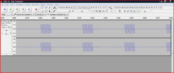
As you have a scope, here is a 1001Hz toneburst which will stress the amp far less than continuous power testing. Measure the peak to peak amplitude across the load resistor at the point visible clipping distortion sets in, and then calculate the RMS voltage. The file is an MP3 which can be burnt to CDR etc or used from an MP3 player as a source.
Example, 23 volts peak to peak across 6 ohms would be 23/2 = 11.5 volts peak. 11.5 olts peak multiplied by 0.707 gives the RMS value (8.1 volts RMS). Watts would be the RMS voltge squared divided by 6 ohms... 11 watts RMS.
Attachments
One way to see the onset of clipping is to use a triangle wave.
The peak clearly shows the onset when viewed on a scope. This assumes a signal generator. Always start with the output level from the signal generator VERY LOW.
The difference in useful power measured right before clipping and somewhat below clipping is minimal.
It is sufficient to see that the output of the amp is able to reach up to or nearly up to the power supply rail voltage on the scope. That verifies that the amp meets the nominal published spec.
You can work that backwards to a nominal power rating merely by measuring the rail voltage and plugging 0.707 of that into the Ohm's law power equation, WRT a nominal load resistance - like 8 ohms.
Testing ur amp into low Z loads is another matter.
One ought to exercise extreme caution in doing this with designs that have limited current capability, since that can over stress the output stage and cause a failure.
_-_-bear
PS. the pulsed signal is a good idea, but again, you need to control the level going INTO the amp, start low... don't "blast" the input (and cause an output failure).
Bear, good point: you really don't need to measure output voltage. Take Vsupply, subtract 2V, that's your Vpeakout ;-)
Pout = ((Vpeakout/1.4)^2)/Rload. Or something like that.
Jan
Pout = ((Vpeakout/1.4)^2)/Rload. Or something like that.
Jan
Bear, good point: you really don't need to measure output voltage. Take Vsupply, subtract 2V, that's your Vpeakout ;-)
Pout = ((Vpeakout/1.4)^2)/Rload. Or something like that.
Jan
Nay nay nay Mr Wilks 😉 That just assumes the amp and PSU are theoretically perfect. When I first started making amps I found it was under load that problems showed... grounding errors mainly, and poor layout.
I can't quite believe I've just read that.
Nay nay nay Mr Wilks 😉 That just assumes the amp and PSU are theoretically perfect. When I first started making amps I found it was under load that problems showed... grounding errors mainly, and poor layout.
I can't quite believe I've just read that.
He wanted to know the output power, not rebuild a nuclear power plant.
Reacting on an answer is easier if you consider the original question ;-)
My answer is within a dB or so.
Jan
Yes, but I only want to measure RMS power output, not THD.
You may have both using my FFT analyzer using a soundcard and the power spectrum bench...
Simple requires:
- a calibrated input
- related attenuation
- configure on amplitude settings: the load resistor
- configure on amplitude settings: external gain/attenuation..
Plots as Watts (linear) or dBW and more..
Hp
He wanted to know the output power, not rebuild a nuclear power plant.
Reacting on an answer is easier if you consider the original question ;-)
My answer is within a dB or so.
Jan
But even so...... this is one we are definitely going to have to agree to disagree over.
But even so...... this is one we are definitely going to have to agree to disagree over.
No we don't disagree, we just are participating in different discussions ;-)
The OP was concerned with how much power his kit built amps were producing.
Assuming they pass a reasonable sinewave, and/or a reasonable triangle wave out to nearly full power (clipping) into a dummy load, then it's really just a matter of converting the B+ rail voltage to power. As Jan said, within a dB or so that result is valid.
IF he was interested in the subtleties (such as they are subtleties) of performance like THD, IM, stability and the like, then we are having a different discussion.
_-_-bear
Last edited:
All very interesting! Thanks to everyone here. I got tied up today with other things but will definitely explore all these methods soon. Just one newby question when measuring the voltage across the dummy load with a cro - where does the cro earth lead go?
Thanks
Thanks
- Status
- Not open for further replies.
- Home
- Design & Build
- Equipment & Tools
- Measuring amp output......how to exactly?