Sorry a bit of a long post but need to get some knowledge from the group before I spend too much more time on this.
I have taken a set of baseline measurements of my 3 my speaker in an anechoic chamber (chamber has a null at 60hz but above 200hz there is no need for gating, very clean data). The measurements taken were -
Using the pairs technique by loading the individual driver measurements and the paired data into VituixCad I can adjust the delays to make the summed individual match the pair data. This results in -
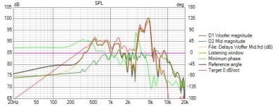
Woofer/Mid - Mid is -270uS which equates to 93mm this is not far from a geometric calculation using Pythagoras (88mm).
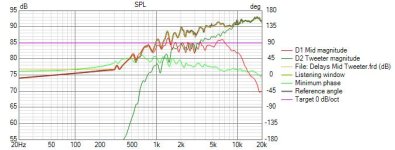
Mid/Tweeter - Tweeter is +20uS which equates to 6.9mm which again sounds about right for a dome mid and dome tweeter.
That said, I modeled up a crossover in VituixCad without adding the offset above, measured the combined speaker response (also with inverted mid to get nulls) and individual driver. The whole speaker model vs measured response matched very well and the step/impulse response also was pretty comparable. Which seems to suggest the data has the acoustic offset embedded in it and my method seems to be correct but something doesn't quite add up with respect to the acoustic offset.
So, the questions is what do I do with the offset data calculated with the pairs approach or have I measured the speaker incorrectly or have I lucked out on my measurements/modelling approach ? Any help will be very welcome and gratefully received, thanks in advance.
For info - if I add in the offsets as delays into VituixCad it is almost impossible to get the phases to line up between the Woofer and Mid.
As an aside after I did this comparison I slightly altered the VituixCad Model2a (2a1) by upping the Tweeter delay to 30uS and slightly changing to the High/Low pass which brought the phases into alignment right up to 15kHz, maintained the flat on axis response and maintained the deep nulls.
I can post the REW mdat files for the three drivers if anyone want to have a play.
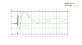
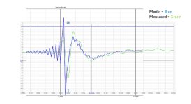
Attached is a number of plots showing:
I have taken a set of baseline measurements of my 3 my speaker in an anechoic chamber (chamber has a null at 60hz but above 200hz there is no need for gating, very clean data). The measurements taken were -
- Microphone at the same position for all, 1m from centre of baffle at tweeter height.
- I had the acoustic timing bleep turned on but this was played through the driver being measured (now I know that you need a second speaker for this to work properly, doh !) therefore all measurements start at 20ms which seems to suggest the data has no acoustic offset built in, is this correct?
- I measured the Woofer (WO24P-4, 40L sealed stand mount monkey box), Mid (EM1308, includes a 39uF protection Cap) and Tweeter (ET448, Includes a 12uF protection Cap) at +/-90,75,60,45,30,20,10,0 degs on the horizontal axis. I did meaure the Mid and Tweeter withouth the protection Caps as well but will be running an active system with them included.
- I also measured the individual drivers and also driver pairs (woofer/mid, mid/tweeter).
- Finally, I did some nearfield measurments for the woofer both on tweeter axis and the woofer axis at 1cm, 30cm, 60cm and 1m.
Using the pairs technique by loading the individual driver measurements and the paired data into VituixCad I can adjust the delays to make the summed individual match the pair data. This results in -
Woofer/Mid - Mid is -270uS which equates to 93mm this is not far from a geometric calculation using Pythagoras (88mm).
Mid/Tweeter - Tweeter is +20uS which equates to 6.9mm which again sounds about right for a dome mid and dome tweeter.
That said, I modeled up a crossover in VituixCad without adding the offset above, measured the combined speaker response (also with inverted mid to get nulls) and individual driver. The whole speaker model vs measured response matched very well and the step/impulse response also was pretty comparable. Which seems to suggest the data has the acoustic offset embedded in it and my method seems to be correct but something doesn't quite add up with respect to the acoustic offset.
So, the questions is what do I do with the offset data calculated with the pairs approach or have I measured the speaker incorrectly or have I lucked out on my measurements/modelling approach ? Any help will be very welcome and gratefully received, thanks in advance.
For info - if I add in the offsets as delays into VituixCad it is almost impossible to get the phases to line up between the Woofer and Mid.
As an aside after I did this comparison I slightly altered the VituixCad Model2a (2a1) by upping the Tweeter delay to 30uS and slightly changing to the High/Low pass which brought the phases into alignment right up to 15kHz, maintained the flat on axis response and maintained the deep nulls.
I can post the REW mdat files for the three drivers if anyone want to have a play.
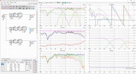
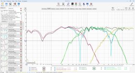
Attached is a number of plots showing:
- Woofer/Mid Offset at Mid= -270uS
- Mid/Tweeter Offset at Tweeter = +20uS
- VituixCad Model2a (my model designation)
- VituixCad Model2a vs Measured full speaker and individual driver responses (note the null at 60hz if from the chamber)
- Step Model2a vs Measured
- Impulse Model2a vs Measured


I'm not sure how Virtuix works, but usually I set the reference point to the driver whose axis I'm measuring on. Usually the tweeter. Everything else has an acoustic offset relative to that. So with Xsim for instance, my tweeters are always 0" delayed but my mid-woofers are often 1.25" or so or more, depending on the driver size and location. In a 3-way I'd expect the woofer to have the most offset.
Be sure to include the safety caps in your simulation for adjusting the offsets.
Using interferometry, that means I leave the tweeter distance alone, and then start to increaase the distance on the mid until the combined output is correct. Then you simulate the mid and woofer, leaving the mid alone and adding offset to the woofer.
In theory, the absolute numbers don't matter as much as the relative offsets from driver to driver.
Also, nothing wrong with designing a speaker on the mid axis instead if that is the driver that will be at ear level. Honestly I think there are some benefits to this approach as well. In this case your mid is 0" / 0uSec and your mic is placed on mid axis.
Last edited:
It is better to measure phase/delay than it is to resort to dealing with offset distances. When doing it this way you don't put values into the offset fields.
As an example to help understand this.. you could use your tweeter as the reference and when you measure the woofer, you have the wires from the amp in hand (using long cables) and switch them after the timing signal but before the measurement signal.I had the acoustic timing bleep turned on but this was played through the driver being measured