
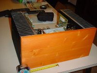
Will be a real Beauty! 🙂 🙂Andypairo said:Just managed to take some photos of my in-progress Aleph 30.
Any comments/suggestions?
Unfortunately I haven't so much spare time so it is going on very slowly....
Cheers Andrea
That warm red/orange colored wood and those black heatsinks
go together perfectly matched in color.
When you are finished you should post your best pictures
to the Pass-Amp Gallery.
/halo - a colorful man fond of nice colors
Thank you, but I believe it will be at its best when putting sone voltage out to the speakers...
By the way I'm already brain-washing my girlfriend about its (rightful) place in our future home!!
Cheers
Andrea
By the way I'm already brain-washing my girlfriend about its (rightful) place in our future home!!
Cheers
Andrea
very nice! i hope it sounds as good as it looks.
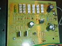
did you do the pcb's yourself? i like the nice big tracks.
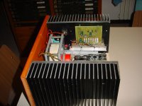
i quite like the transformer mounting, too.
very nice all round. i wish i could make stuff that good looking.
hope all goes well!
did you do the pcb's yourself? i like the nice big tracks.
i quite like the transformer mounting, too.
very nice all round. i wish i could make stuff that good looking.
hope all goes well!
Hamish said:very nice! i hope it sounds as good as it looks.
did you do the pcb's yourself? i like the nice big tracks.
i quite like the transformer mounting, too.
very nice all round. i wish i could make stuff that good looking.
I did PCBs by myself but using a layout given to me by a fellow Italian DIYer; the front end of most Alephs is identical, you only need different output stages (and of course different values of components..)
Cheers
Andrea
I hope you have some more free time. It looks very nice. How about some details. Power supply? Caps? What kind of outputs and what bias? Good work.
You gotta be hot to be real cool...
Looks great! Be careful though that the transformer doesn't get to hot seeing you have both sides of it covered up. You can measure the temperature rise above ambient accurately by checking the primary winding resistance cold and then hot. Here's a spreadsheet to help you do this.
Looks great! Be careful though that the transformer doesn't get to hot seeing you have both sides of it covered up. You can measure the temperature rise above ambient accurately by checking the primary winding resistance cold and then hot. Here's a spreadsheet to help you do this.
Attachments
MikeW said:I hope you have some more free time. It looks very nice. How about some details. Power supply? Caps? What kind of outputs and what bias? Good work.
I hope that too...
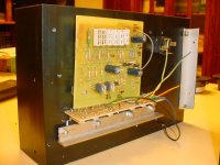
I'm still deciding about the power supply: on the pictures tou can see a rectifier bridge (35 A) on each heatsink, so 2 bridges.
After that I have 2x22000 uF common to both channels, and after these 2x30000 uF (the capacitor arrays you can see on photos) per channel.
My doubt is about inserting chokes between the condensers since I have only 2 suitable air-core inductors (1,2 mH, 0,33 ohm) and the condensers that feed each channel would be in parallel.
Transformer is 2x 22Vac, 500VA; a bit high in voltage but these heatsinks allow me to reach a higher power, so I don't care.
Output devices are matched IRFP150, six per channel (3+3), bias is around 2,5 A.
I guess the only way to go is .. to try!!
Cheers
Andrea
Re: You gotta be hot to be real cool...
Thank you, I'll check it out
Cheers
Andrea
Circlotron said:Looks great! Be careful though that the transformer doesn't get to hot seeing you have both sides of it covered up. You can measure the temperature rise above ambient accurately by checking the primary winding resistance cold and then hot. Here's a spreadsheet to help you do this.
Thank you, I'll check it out
Cheers
Andrea
italian design
IMHO italian design is the best:
Pininfarina, Ferrari, Ducati, Armani, Your amp...
Uli
IMHO italian design is the best:
Pininfarina, Ferrari, Ducati, Armani, Your amp...
Uli
Fortunately Italy is known worldwide not only for  , pizza and mandolino!
Apart from jokes, you make me blush
I had to make it "beautiful" to increase its future WAF...you know girls don't usually like ugly things in the living room, even if they sound ..
..
Cheers
Andrea
, pizza and mandolino!Apart from jokes, you make me blush
I had to make it "beautiful" to increase its future WAF...you know girls don't usually like ugly things in the living room, even if they sound
..Cheers
Andrea

Faber said:Spettacolo!
Posso vederlo da vivo?

Ops, sorry...
Spectacular, May I see it live?
😉
Bye
Certo, dammi il tempo di finirlo, cosi potrai anche sentirlo...

Yep, just give me the time to finish it, so you'll be able to listen to it too...
Cheers
Andrea
I may be ugly, but at least I'm not big. Then again, my wife
puts up with El Pipe-O. Hmmmmm....
Beautiful amp.
😎
puts up with El Pipe-O. Hmmmmm....
Beautiful amp.
😎


- Status
- Not open for further replies.
- Home
- Amplifiers
- Pass Labs
- Me too... me too.. pics of my DIY Aleph 30