I have a 1972 McIntosh MR77 tuner.
I broke off 2 pins (#1, #14 I think) on the Motorola 14 pin IC on the MPX circuit board while I was giving it a thorough cleaning. (Please don't scold me for my ignorance...I feel bad about it)
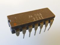
It is IC 301 on their technical manual (part #133-004) located on the MPX circuit board in the rear left of the tuner.
Does someone know what IC this is? (Attached is a photo of it)
I can buy it for $40+$8 shipping from Mac. I want to see if I can get it cheaper, especially since I can't afford to have it aligned either (it only picks up 6 strong stations).
A member of another forum said it is 'comercial number motorola mc1303' integrated circuit. I see there are various versions of this IC and maybe there are better substitutes too.
Humbly,
I broke off 2 pins (#1, #14 I think) on the Motorola 14 pin IC on the MPX circuit board while I was giving it a thorough cleaning. (Please don't scold me for my ignorance...I feel bad about it)
It is IC 301 on their technical manual (part #133-004) located on the MPX circuit board in the rear left of the tuner.
Does someone know what IC this is? (Attached is a photo of it)
I can buy it for $40+$8 shipping from Mac. I want to see if I can get it cheaper, especially since I can't afford to have it aligned either (it only picks up 6 strong stations).
A member of another forum said it is 'comercial number motorola mc1303' integrated circuit. I see there are various versions of this IC and maybe there are better substitutes too.
Humbly,
Attachments
No ideas for source or subsitutes, but if you are reasonably skilled at soldering, you can easily do some electronic first aid...
snip two pins off another donor IC and solder them to that chip.....
put the IC in it's socket(?), set the two missing pins and give them a SMALL blob of solder - wait at least 10 sec's between the the two joints....
snip two pins off another donor IC and solder them to that chip.....
put the IC in it's socket(?), set the two missing pins and give them a SMALL blob of solder - wait at least 10 sec's between the the two joints....
It did cross my mind to solder two pins on to the IC. So you recommend putting the missing pins and the IC in the socket, then solder in place? I was thinking of doing it upside down on a counter.
If you can manage to make them stick correctly, solder outside the socket.
If you solder with the IC and pin in the socket , work quickly but properly ,- meaning: do not overheat or use excessive solder...... done it a few times some years ago....
If you solder with the IC and pin in the socket , work quickly but properly ,- meaning: do not overheat or use excessive solder...... done it a few times some years ago....
I'm guessing that the chip may be a MC1309.
Data sheet here:
MC1310 Datasheet PDF,MC1310 Circuit,MC1310 Manual - Soiseek
See if the pin functions appear to line up. Would probably be hard to find now. There were a few more multiplex decoder chips made - which may actually have an identical - or close pin layout. Do a search under multiplex decoder IC's and see what you find - then good luck in sourcing the part.
Charles
My 1979 Motorola linear ic databook has the MC1310 as the standard stereo demodulator. NTE makes a replacement.
Ray
http://nte01.nteinc.com/nte%5CNTExRefSemiProd.nsf/$all/6BE0CF16669514578525791000819E2E?OpenDocument
Ray
http://nte01.nteinc.com/nte%5CNTExRefSemiProd.nsf/$all/6BE0CF16669514578525791000819E2E?OpenDocument
Last edited:
Hi,
if your pic shows your problem, i'd follow AuroaB's advice instead of looking for a substitute or replacement IC. You don't even need a 'donor IC', just solder two short pieces of thin wire to the remainders of the broken pins. There's pretty enough area to do so.
Good luck!
if your pic shows your problem, i'd follow AuroaB's advice instead of looking for a substitute or replacement IC. You don't even need a 'donor IC', just solder two short pieces of thin wire to the remainders of the broken pins. There's pretty enough area to do so.
Good luck!
Last edited:
I see mention of sockets... if the IC were in a socket originally then I would remove it and solder direct to the PCB. Just use a resistor leg soldered in to the pcb and it will pass up alongside the missing legs where it can be soldered. Snip to length when soldered and you wont even see it. Or use thin wire.
Have to ask 🙂 how on earth did you break the legs cleaning a populated board.
Have to ask 🙂 how on earth did you break the legs cleaning a populated board.
Thanks for all the help. I'm a little nervous and not as knowledgeable as you folks. Are any of these IC recommendations a direct replacement or improvement, and I should not worry if I use a MC1303, MC1309, or MC1303. Will I cause harm if I put the incorrect IC in?
Hi,
if your pic shows your problem, i'd follow AuroaB's advice instead of looking for a substitute or replacement IC. You don't even need a 'donor IC', just solder two short pieces of thin wire to the remainders of the broken pins. There's pretty enough area to do so.
Good luck!
That seems simple enough for me. Should I look for a piece of copper solid wire that will hold in the socket firmly and flatten it with pliers to shape?
Also does the red dot on the IC indicate pin #1 so I can position correctly?
Last edited:
You can order the NTE801 from Mouser. It is a direct replacement for the MC1310.
Ray
Mouser Electronics - Electronic Component Distributor nte801
Ray
Mouser Electronics - Electronic Component Distributor nte801
Red dot in picture is pin 1
If this thing goes into a socket I personally would be happier if it were all soldered in place (socket removed). As long as the board is single sided it's 2 minutes of a job with solder braid to remove the old socket.
If this thing goes into a socket I personally would be happier if it were all soldered in place (socket removed). As long as the board is single sided it's 2 minutes of a job with solder braid to remove the old socket.
Hold on a minute here. I said that the 1310 MAY be the chip used in the 77. You have to do some comparison of what is connected to similar pins between the tuner schematic and the "typical" schematic on the data sheet.
ALSO, there were at least two "generations" of IC multiplex decoder chips, with the "later" chips having much lower distortion and other characteristics. Think the 1310 may be the "older" design.
I don't remember any "newer" chip numbers (maybe the LM1800??). However if you HAVE to replace the chip, I'd do some research and see how compatible one of the newer chips might be (and where they may be available).
The 77 is a nice tuner - and worth the effort.
Charles
Thanks for your kindness. So much good advice given to me. What a great sight this is, even for a novice like me.
This seems very good. Is this IC a replacement for the one I'm removing. I've had recommendations of 1303, 1309, and 1310. Are they all the same with the pins connecting to what they should.
Thanks. This seems doable for me. What are the benefits?Red dot in picture is pin 1
If this thing goes into a socket I personally would be happier if it were all soldered in place (socket removed). As long as the board is single sided it's 2 minutes of a job with solder braid to remove the old socket.
You can order the NTE801 from Mouser. It is a direct replacement for the MC1310.
Ray
Mouser Electronics - Electronic Component Distributor nte801
This seems very good. Is this IC a replacement for the one I'm removing. I've had recommendations of 1303, 1309, and 1310. Are they all the same with the pins connecting to what they should.
Hold on a minute here. I said that the 1310 MAY be the chip used in the 77. You have to do some comparison of what is connected to similar pins between the tuner schematic and the "typical" schematic on the data sheet.
ALSO, there were at least two "generations" of IC multiplex decoder chips, with the "later" chips having much lower distortion and other characteristics. Think the 1310 may be the "older" design.
I don't remember any "newer" chip numbers (maybe the LM1800??). However if you HAVE to replace the chip, I'd do some research and see how compatible one of the newer chips might be (and where they may be available).
The 77 is a nice tuner - and worth the effort.
Charles
Ok, I will try to see if I can figure it out.
For what it's worth, according to Terry DeWick on an old post on another forum, the IC is a LM1303N and used on both the MR77 and MR78. Does this seem correct?
BTW I soldered two wire ends on the missing pins. Tuner seems to work as well as before (which is only the strong stations pulling in - need of alignment), except now 2 stations tune in (all the lights, meters, and indicators work), but these stations have no sound. All other working stations play fine. Any ideas?
BTW I soldered two wire ends on the missing pins. Tuner seems to work as well as before (which is only the strong stations pulling in - need of alignment), except now 2 stations tune in (all the lights, meters, and indicators work), but these stations have no sound. All other working stations play fine. Any ideas?
Last edited:
If there is any doubt over what the IC may or may not be then don't even think about trying one to see.
If all that is wrong with the one you have is the damaged legs then it can fitted and fixed in minutes.
Have you ever used solder braid before ?
This shows how braid wicks up the solder,
http://www.diyaudio.com/forums/parts/127924-working-smd-how-do-without-specialised-tools.html
If all that is wrong with the one you have is the damaged legs then it can fitted and fixed in minutes.
Have you ever used solder braid before ?
This shows how braid wicks up the solder,
http://www.diyaudio.com/forums/parts/127924-working-smd-how-do-without-specialised-tools.html
For what it's worth, according to Terry DeWick on an old post on another forum, the IC is a LM1303N and used on both the MR77 and MR78. Does this seem correct?
The LM1303 is a preamp chip I think. Not an MPX decoder.
The National Semiconductor Audio Radio Handbook shows the LM1303 as a preamp and also the LM1310 as a stereo demodulator. The LM1310 was National's version of the Motorola MC1310.
Ray
National Semiconductor Audio/Radio Handbook - book contents list
Ray
National Semiconductor Audio/Radio Handbook - book contents list
with some skill and practice you can solder the broken pins directly to the socket, don't know if the pcb provides enough space for handling the iron though...
- Status
- Not open for further replies.
- Home
- Source & Line
- Analogue Source
- McIntosh MR77 tuner - IC needed for MPX board