I'm trying to match a pair of BC550's for the input to my ExtremeA.
I understand that matching hfe is not the ultimate goal and that many prefer to match Vbe as well. So I am trying to match both.
I have built a jig basically using this NPN schematic and a DIP socket to easily swap out transistors-
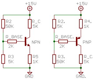
After reading a few threads here, I am a little confused about what reading is important. Is it the voltage across the base resistor or just a measurement of Vbe directly (shouldn't it always be = .7?)
I understand that matching hfe is not the ultimate goal and that many prefer to match Vbe as well. So I am trying to match both.
I have built a jig basically using this NPN schematic and a DIP socket to easily swap out transistors-
After reading a few threads here, I am a little confused about what reading is important. Is it the voltage across the base resistor or just a measurement of Vbe directly (shouldn't it always be = .7?)
Matching tester
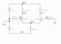
This circuit is a lot like many front ends. All the resistors are 10K. The collector voltages (nodes 1 and 2) should be very similar, about 7.5 Volts. However, the important measure of matching is the voltage difference between nodes 1 and 2. The circuit weights Vbe and beta matching in a way not too unlike a typical input stage...of course, "your mileage may vary", but I still think that this circuit, or something like it, would be useful.
This circuit is a lot like many front ends. All the resistors are 10K. The collector voltages (nodes 1 and 2) should be very similar, about 7.5 Volts. However, the important measure of matching is the voltage difference between nodes 1 and 2. The circuit weights Vbe and beta matching in a way not too unlike a typical input stage...of course, "your mileage may vary", but I still think that this circuit, or something like it, would be useful.
Attachments
That circuit will let you measure hfe as the ratio of current through R_C to the current through R_BASE. If you want to measure Vbe, you should measure it at a fixed collector current.
In both cases, you should try to measure the transistors under similar conditions (Ic, Vce) as they will encounter in their intended use.
In both cases, you should try to measure the transistors under similar conditions (Ic, Vce) as they will encounter in their intended use.
***If you want to measure Vbe, you should measure it at a fixed collector current.
In both cases, you should try to measure the transistors under similar conditions (Ic, Vce) as they will encounter in their intended use.
Does that mean that you should use a variable resistor for the base resistor and adjust collector current to be the same, then probe Vb and Ve to take the voltage there?
if the two transistors match then the collector currents will be the same. You don't need an adjustable base resistor or adjustable any resistor.
I and Anatech disagree on the precise details of this matching, but we are very close in practice.
10k is far too high for collector load resistors.
I prefer the tail to be a CCS that can be stepped through a variety of fixed tail currents.
The two devices must be thermally coupled together.
The Vce must be equal.
The Vbe must be equal.
The Id must be equal.
You would like the Ib to be as near as equal as you are prepared to tolerate, (somewhere between 1% and 10% difference).
With all these equalities across the LTP then Pq must be equal and thus Tj must be equal.
Now, the difference between Anatech & I.
If the Ib is not equal, the Vrb will differ. This voltage drop difference will guarantee that the two transistors have a different Vbe. If the Vbe of the transistors is not precisely equal then there is little point in continuing with the match experiment.
I initially had two matched pairs of switched base resistors, 10k and 1k0 +-0.1%. on changing from the Rb=10k to Rb=1k0 the matching went haywire.
Reducing Rb to 100r made the matching even worse. Now device temperatures and voltage drops and currents were miles from equal.
I realised that the Vbe of both devices must be precisely equal and this requires that the two emitters be tied together and the two bases are tied together. This allows matching of Vbe vs Ic alone. This also requires the Rb=0r0.
Take the matched sets (for Vbe vs Iq) and replace/switch Rb=1k0 and compare to find the matched pairs. If Ib are equal and Ic are equal, then you have a matched pair.
As a final check, you can adjust Vbe slightly such that Ic varies a bit either side of Iq and see how well the match holds up when the two devices track with varying IC. This needs the CCS to be switched out and resistor tail substituted.
You now have a pair of devices that have matched hFE and Vbe for a range of Ic either side of Iq.
Ps, I use a single polarity PSU and feed the base resistors from an auto biasing resistor. Change the PSU voltage to change the Ib and the CCS holds Ic near constant (it actually holds Ie constant).
Interesting....
What is an 'auto biasing resistor'? I assume you're taking about some kind of active circuit to generate GND? Got a circuit for that you can provide please?
Cheers,
Andy
I use a single polarity PSU and feed the base resistors from an auto biasing resistor
What is an 'auto biasing resistor'? I assume you're taking about some kind of active circuit to generate GND? Got a circuit for that you can provide please?
Cheers,
Andy
omit R3 from post1.
The base current is [Vcc-Vbe]/[Rb+R1]
With a variable PSU you can adjust the Ib without any resistor changes. That allows you to trim the Ic
If you don't have a Variable PSU then you can make the 50k (R2) a 100k pot wired as a VR.
The base current is [Vcc-Vbe]/[Rb+R1]
With a variable PSU you can adjust the Ib without any resistor changes. That allows you to trim the Ic
If you don't have a Variable PSU then you can make the 50k (R2) a 100k pot wired as a VR.
^ pot the 50K to GND, wiper to base, other end to +20V. Make 10K 150R.
See also
http://www.diyaudio.com/forums/showthread.php?t=146693&page=73
See also
http://www.diyaudio.com/forums/showthread.php?t=146693&page=73
- Status
- Not open for further replies.
- Home
- Amplifiers
- Solid State
- Matching BC550C BJTs